Auto-setting and optimization of EAM with optical line systems

a technology of optical communication system and auto-setting, applied in the direction of transmission monitoring, transmission monitoring/testing/fault measurement system, electrical equipment, etc., can solve the problems of not being able to provide a cost effective or efficient means, not being able to provide a means for tuning the whole system to an optimal operating condition, and little done in the field to investigate effective deployment and configuration. , to achieve the effect of improving system performance, improving search resolution, and improving the performance of optical links

Inactive Publication Date: 2005-11-29
OPLINK COMM
View PDF11 Cites 98 Cited by
  • Summary
  • Abstract
  • Description
  • Claims
  • Application Information

AI Technical Summary

Problems solved by technology

However, there has been, to this point, very little done in the field to investigate the effective deployment and configuration, of these new technologies, that would allow for the optimization of the end-to-end system performance in a closed loop configuration.
However, as the art progresses and increased data-rates are demanded these localized control loops will not be able to provide a cost effective or efficient means for designing reliable high-speed optical communication links, and does not provide a means for tuning of the whole system to an optimal operating condition.
The above-discussed problems exist in both single-span and multiple span optical links.

Method used


Image

  • Auto-setting and optimization of EAM with optical line systems
  • Auto-setting and optimization of EAM with optical line systems
  • Auto-setting and optimization of EAM with optical line systems

Examples


Embodiment Construction

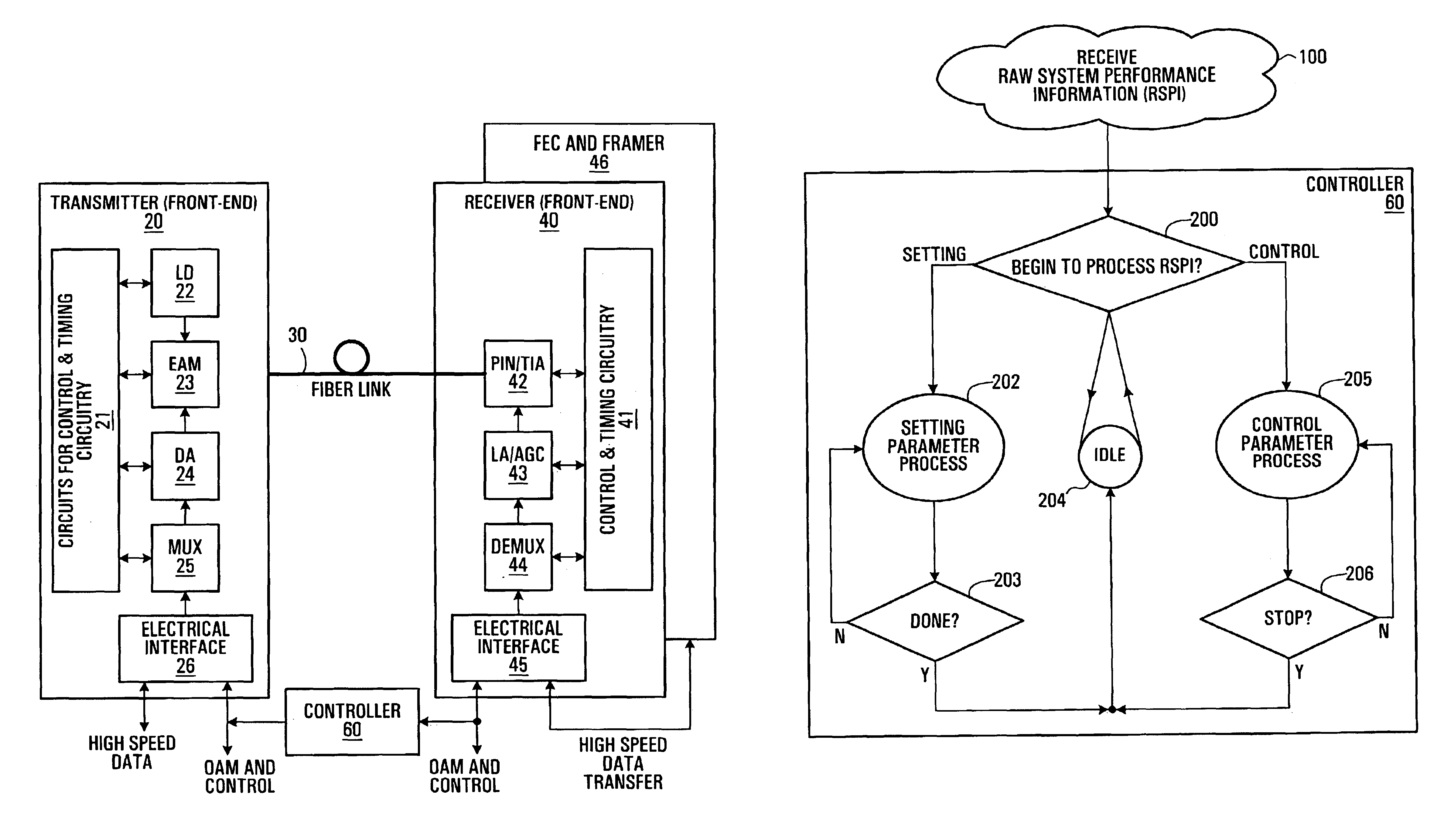
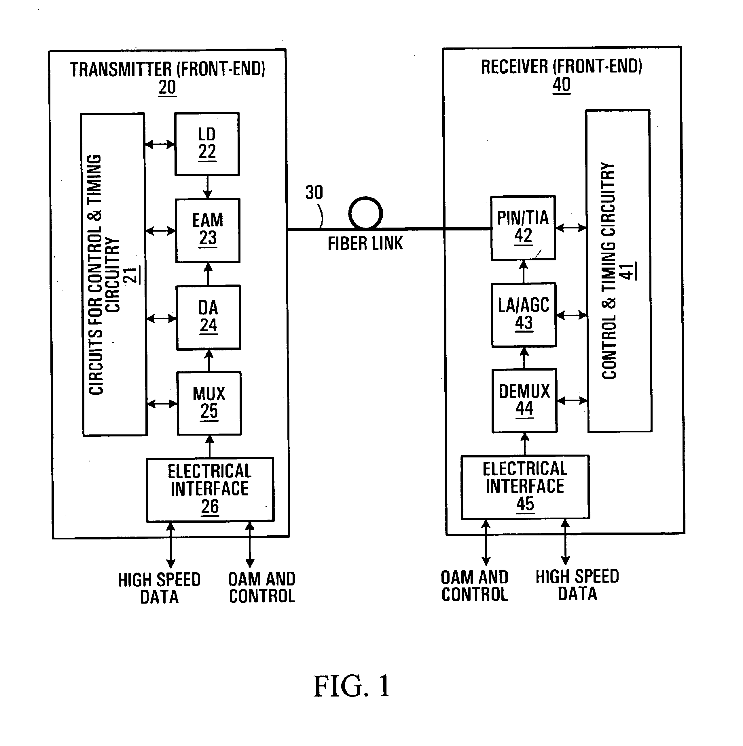
[0027]Referring to FIG. 1, a typical single transmitter and receiver optical transmission system consists of a transmitter front-end module 20 which is connected via an optical fiber link 30 to a receiver front-end module 40.

[0028]More particularly, the transmitter front-end module 20 is a collection of a number of functional blocks and in this description only the blocks most relevant to the invention are discussed. The functional blocks important to the invention are: an N×1 multiplexer (MUX) 25 used to combine a number N parallel electrical low bit rate signals each representing a bit stream, for example with a bit rate of 2.5 Gbps each, into one serial electrical high bit rate signal also being a bit stream, for example with a 40 Gbps bit rate; a laser diode (LD) 22; a driver amplifier (DA) 24; an electronic absorption modulator (EAM) 23; a logic-gate array 21 used to implement the control and timing circuitry for the transmitter front-end module; and finally, an electrical inte...


PUM


Abstract

According to the invention there is provided a method of controlling an optical communication system comprising an optical transmitter, an optical receiver and an optical fiber interconnecting the optical transmitter and the optical receiver, the method comprising determining the performance of the optical communication system and controlling at least one setting parameter of the optical transmitter according to the measured performance.

Description

[0001]This application claims the benefit of U.S. Provisional Application No. 60 / 336,714, filed Dec. 7, 2001.FIELD OF THE INVENTION[0002]This invention relates to the end-to-end performance optimization of an optical communication system.BACKGROUND OF THE INVENTION[0003]Optical communication systems are at the core of modern telecommunications. They provide performance in terms of speed, capacity and reliability that make them an indispensable technology within the global communications infrastructure. To that end countless optical / electrical (opto-electronic) technologies have been developed to support the transmission and reception of optical signals through optical fiber channels. However, there has been, to this point, very little done in the field to investigate the effective deployment and configuration, of these new technologies, that would allow for the optimization of the end-to-end system performance in a closed loop configuration.[0004]In conventional transmitter and rece...

Claims


Application Information

Patent Timeline
Patent Type & Authority Patents(United States)
IPC IPC(8): H04B10/02H04B10/08
CPCH04B10/0795H04B10/07953H04B10/0799
Inventor ZHANG, GENZAOFU, XIAOLISHI, FENGWANG, TONGQINGLI, JINGHUI
Owner OPLINK COMM
Why Eureka
Try Eureka