System and method for color mixing lens array

a color mixing and lens array technology, applied in the field of optical systems, can solve the problems of current systems suffering efficiency losses, efficiency losses of approximately 10% or greater, current systems suffering conversion losses, etc., and achieve the effects of reducing or preventing the heat of the led chip, reducing or preventing the loss of efficiency, and increasing the phosphor conversion efficiency

Inactive Publication Date: 2013-11-19
ILLUMITEX INC
View PDF544 Cites 58 Cited by
  • Summary
  • Abstract
  • Description
  • Claims
  • Application Information

AI Technical Summary

Benefits of technology

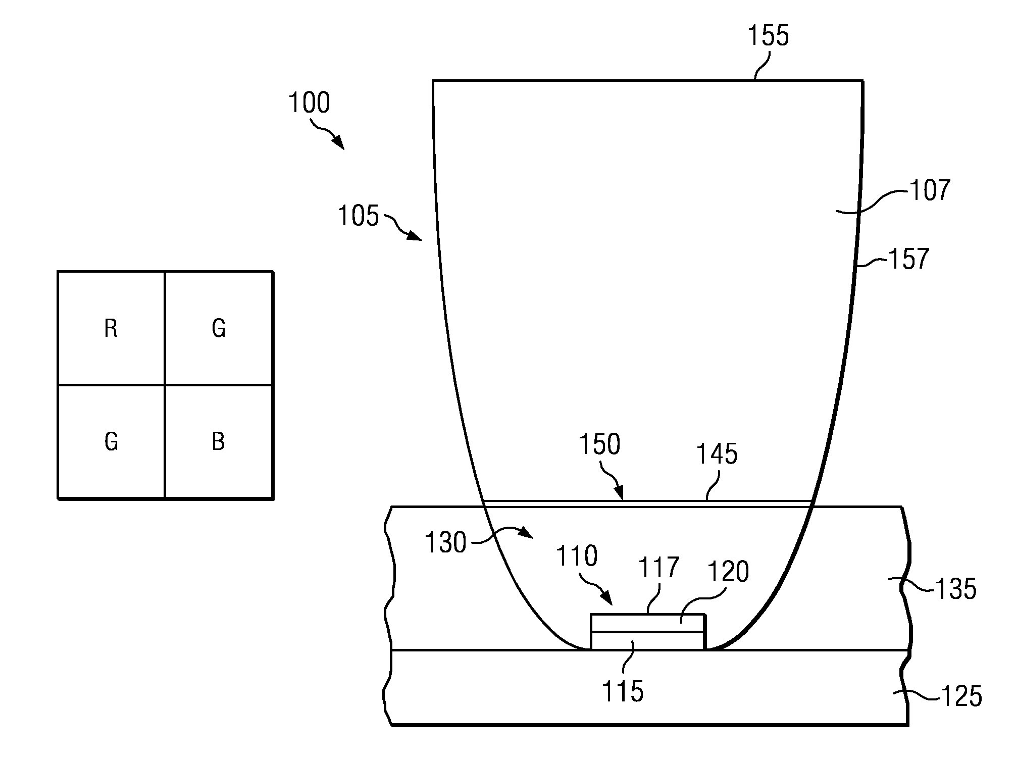
[0010]One advantage provided by embodiments described herein is that phosphor is removed from the LED chip. Heating of the LED chip is therefore reduced or prevented.
[0011]As another advantage, phosphor conversion efficiency can be increased due to the separation of phosphor from the LED active layer. Self-heating of phosphor due to the Stokes shift can be suppressed by heat dissipation through the system submount / heatsink.
[0012]As yet another advantage, higher phosphor conversion efficiency can be achieved due to the lowered flux density at the entrance of the lens, as compared to the flux density at the LED chip.
[0013]As another advantage of various embodiments, positioning phosphor at the entrance surface of a brightness conserving separate optical device can provide an optimal balance between thermal consideration and effective phosphor package efficiencies.
[0014]As yet another advantage, light beam pattern control, color mixing and color conversion can be achieved at the same optical device.
[0015]Embodiments can provide another advantage by providing a uniform spatial distribution at far field using a brightness conserving lens, making it possible for the underlying optical system to conserve the etendue of the source. Embodiments of described herein provide another advantage by allowing for near and / or far field color and spatial uniformity or for near and / or far field tailored color distribution and spatial distribution.

Problems solved by technology

Current systems suffer efficiency losses due to heating of the LED chip and the phosphor particles.
The coupling of a lens to a dome causes efficiency losses of approximately 10% or greater.
Furthermore, current systems suffer conversion losses when multiple color phosphors are used due to cross-excitation.
For instance, a red-emitting phosphor may absorb down-converted light from a green-emitting phosphor instead of the pump wavelength, thereby introducing further losses.

Method used


Image

  • System and method for color mixing lens array
  • System and method for color mixing lens array
  • System and method for color mixing lens array

Examples


Embodiment Construction

[0048]Embodiments and various features and advantageous details thereof are explained more fully with reference to the exemplary, and therefore non-limiting, examples illustrated in the accompanying drawings and detailed in the following description. Descriptions of known starting materials and processes may be omitted so as not to unnecessarily obscure the disclosure in detail. It should be understood, however, that the detailed description and the specific examples, while indicating the preferred embodiments, are given by way of illustration only and not by way of limitation. Various substitutions, modifications, additions and / or rearrangements within the spirit and / or scope of the underlying inventive concept will become apparent to those skilled in the art from this disclosure.

[0049]As used herein, the terms “comprises,”“comprising,”“includes,”“including,”“has,”“having” or any other variation thereof, are intended to cover a non-exclusive inclusion. For example, a process, produ...


PUM


Abstract

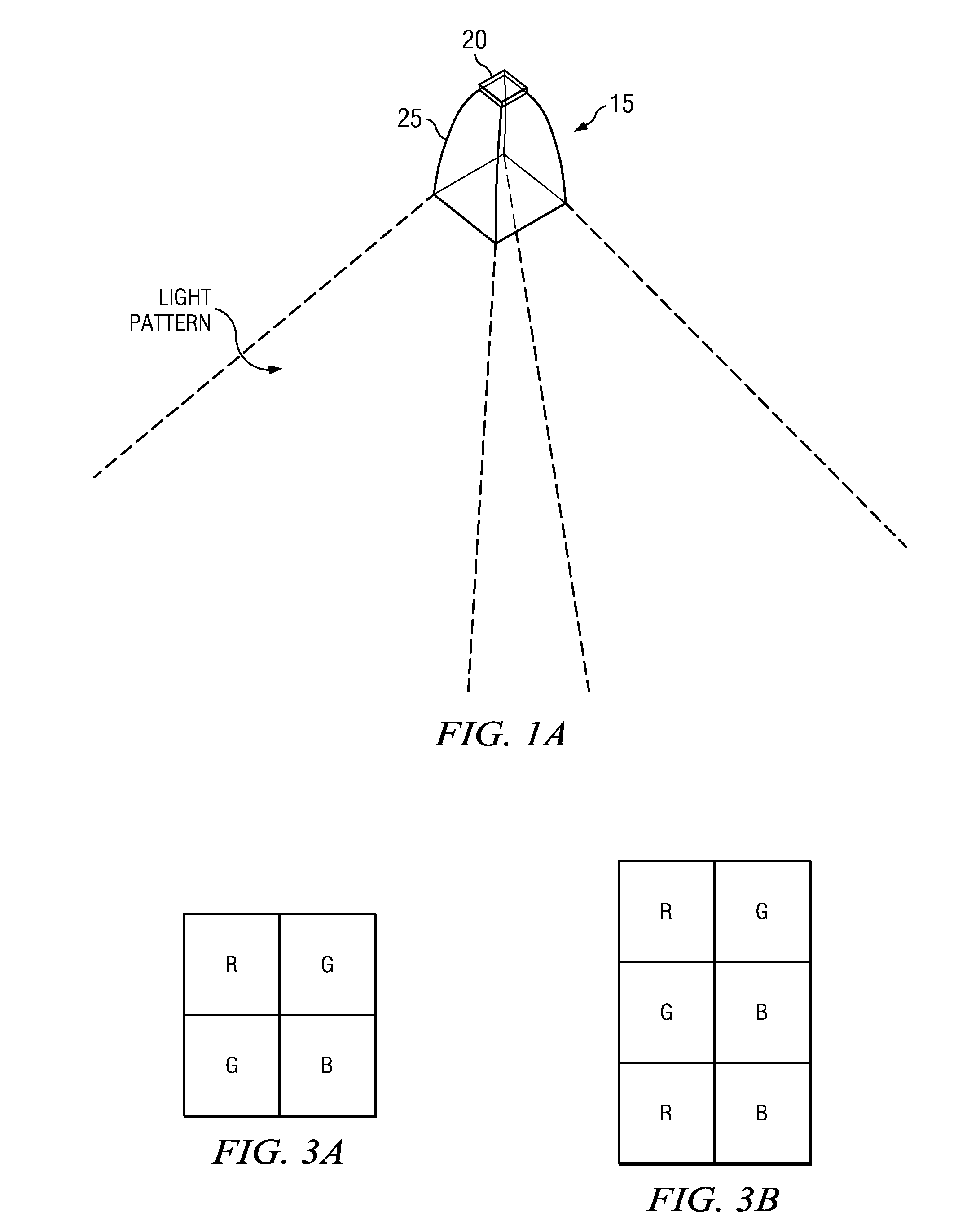
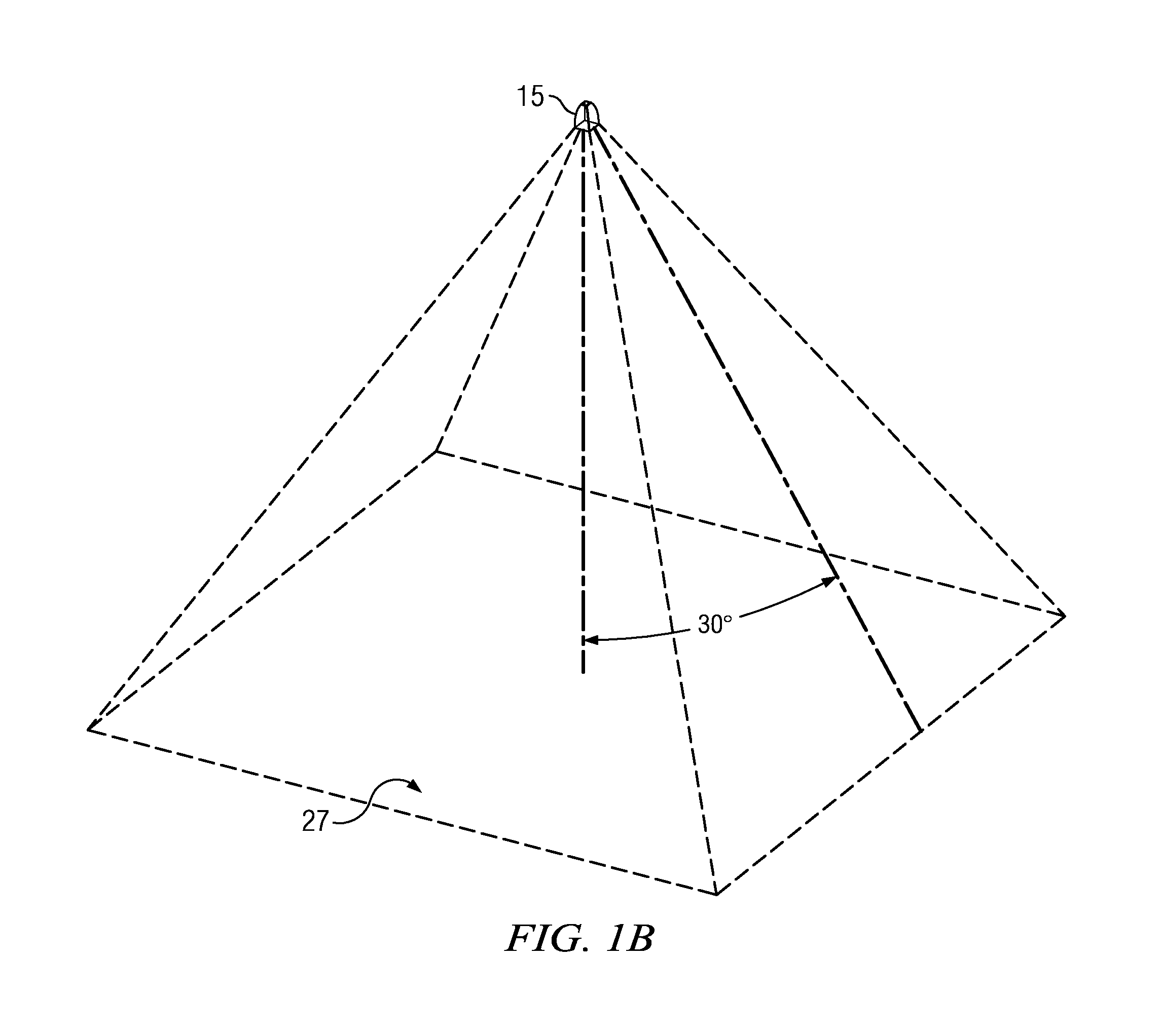
Embodiments described herein provide optical systems that can mix colors to produce illumination patterns having a large area with uniform color. One embodiment of an optical system can include a set of optical units that each produces an illumination pattern with uniform color and intensity. The optical units are spaced so that the individual illumination patterns overlap to create an overall illumination pattern with an overlap area. In the overlap area, the colors emitted by the individual optical units mix to create a desired color. Embodiments of optical systems can provide beam control so that the optical units emit a high percentage of light in beam.

Description

RELATED APPLICATIONS[0001]This application claims priority under 35 U.S.C. 119(e) to U.S. Provisional Patent Application No. 61 / 319,739 entitled “System and Method for Phosphor Coated Lens” by Ko et al., filed Mar. 31, 2010 and under 35 U.S.C. 120 as a continuation-in-part of U.S. patent application Ser. No. 12 / 646,570 entitled “System and Method for a Phosphor Coated Lens” by Ko et al., filed Dec. 23, 2009, which claims priority to U.S. Provisional Patent No. 61 / 235,491 entitled “Phosphor Coated Lens for Phosphor Converting Type White Light Engine” by Ko et al., filed Aug. 20, 2009. Each of the applications referenced above in this paragraph is hereby fully incorporated by reference herein.TECHNICAL FIELD OF THE DISCLOSURE[0002]The present disclosure relates generally to optical systems. More particularly, the present disclosure relates to using arrays of optical units to create highly uniform light distributions with selected color and / or color temperature.BACKGROUND OF THE DISCLO...

Claims


Application Information

Patent Timeline
Patent Type & Authority Patents(United States)
IPC IPC(8): F21V33/00
CPCA01G7/045F21V13/04C09K11/7734C09K11/7774F21K9/56F21V5/007F21V5/04F21V7/0091G02B3/0056F21V13/02C09K11/0883F21Y2101/02F21Y2105/003F21Y2113/005H01L33/58F21Y2105/12F21Y2105/10F21K9/64F21Y2115/10F21Y2113/13A01G9/249Y02P60/14
Inventor DUONG, DUNG T.KO, HYUNCHULJOHNSON, RANDALL E.WINBERG, PAUL N.RADKOV, EMIL
Owner ILLUMITEX INC
Why Eureka
Try Eureka