Angle panel

a technology of telecommunications applications and panels, applied in the direction of two-part coupling devices, network connectors, coupling device connections, etc., can solve the problems of change of electrical properties, core wire breaking or component damage, and various prior art designs are still not satisfactory in function, and achieve the effect of convenient installation and inexpensive fabrication

Active Publication Date: 2013-11-19
JYH ENG TECH
View PDF25 Cites 14 Cited by
  • Summary
  • Abstract
  • Description
  • Claims
  • Application Information

AI Technical Summary

Benefits of technology

[0015]The present invention has been accomplished under the circumstances in view. It is main object of the present invention to provide an angle panel for holding network jacks for the connection of mating network plugs, which is easy to install and inexpensive to fabricate.
[0016]It is another object of the present invention to provide an angle panel for holding network jacks for the connection of mating network plugs, which facilitates arrangement of network cables in a wire organizer, avoids core wire damage and maintains excellent electrical characteristics.
[0018]In an alternate form of the present invention, the angle panel comprises a panel body comprising a flat base and a plurality of openings cut through the flat base for holding in each opening of the panel body one respective network jack having an upper hook and a lower hook for mounting and a plug hole for receiving a mating network plug, and a retaining backboard affixed to the back side of the panel body for securing respective network jacks in the openings of the panel body. The retaining backboard comprises a first retaining structure and a second retaining structure corresponding to each opening of the panel body for engagement with the upper hook and lower hook of one respective network jack to keep the respective network jack at the angle panel at an oblique angle.

Problems solved by technology

At this time, the cable or network line at the back side of the plug will be heavily curved, easily leading to core wire breaking or component damage, or causing change of electrical properties.
The aforesaid various prior art designs are still not satisfactory in function and have drawbacks as follows:
The structure of U.S. Pat. No. 6,537,106 is excessively complicated, not easy to assemble in the production line.
U.S. Pat. Nos. 6,866,541 and 7,300,308 have the common drawback that the panel protrudes over the rack, and wiring technicians may be injured by the protruding part of the panel accidentally.
U.S. Pat. No. 7,488,205 has the drawback that, due to that the ports open in an angled direction toward a lateral side of the bezel, the fabrication of the patch panel requires techniques, increasing the manufacturing cost.

Method used


Image

  • Angle panel
  • Angle panel
  • Angle panel

Examples


Embodiment Construction

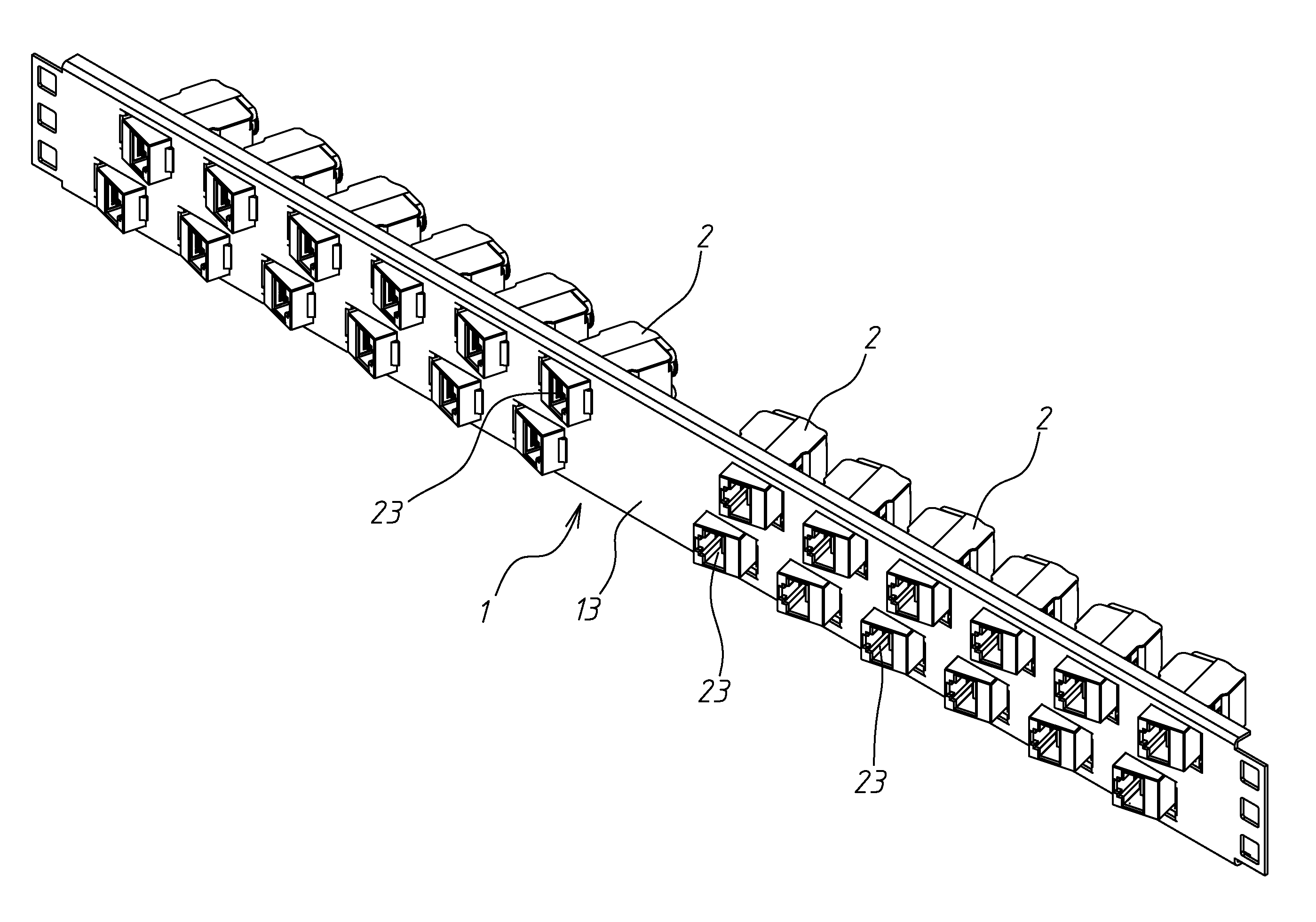
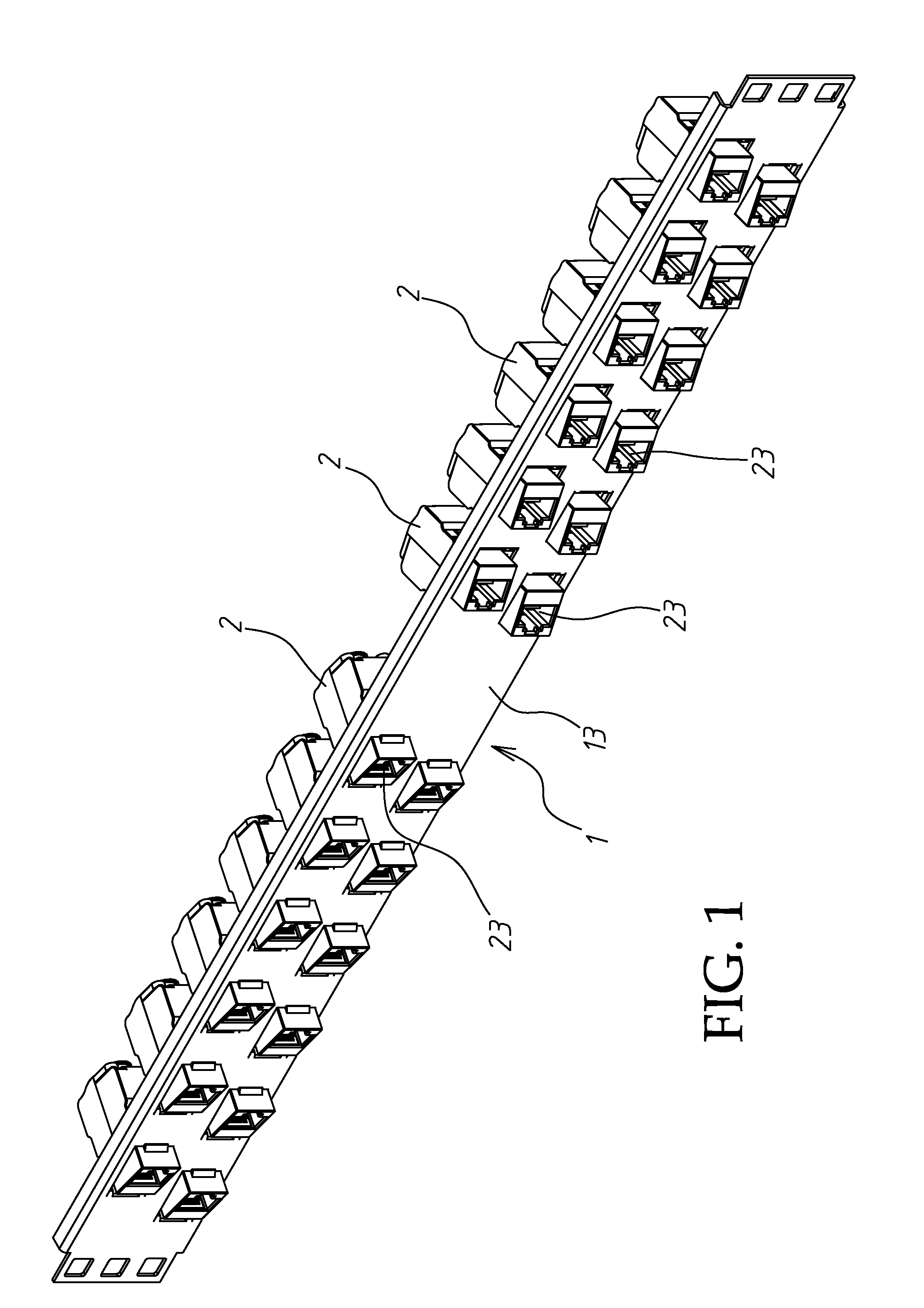
[0027]Referring to FIG. 1, an angle panel 1 in accordance with a first embodiment of the present invention generally is show for the mounting of a plurality of network jacks, for example, keystone jacks 2.

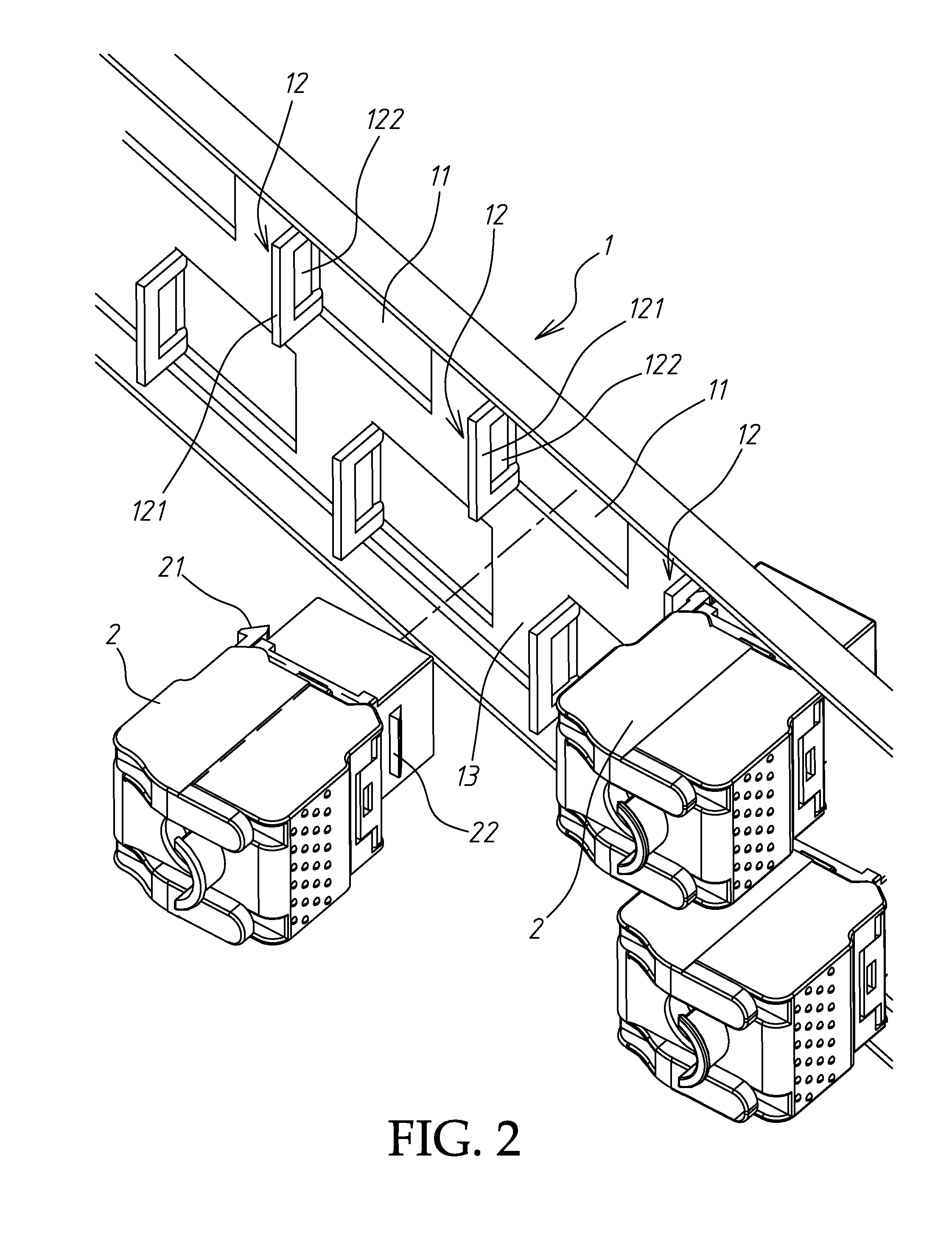
[0028]Referring to FIGS. 2 and 3 and FIG. 1 again, the angle panel 1 defines a flat base 13, a plurality of openings 11 cut through the flat base 13, a retaining structure 12 located on one side of each opening 11 and extending backwardly relative to the plane 1. Each retaining structure 12 has a planar surface 121 that defines with the flat base 13 of the angle panel 1 a contained angle α°, as shown in FIG. 3, for securing one respective keystone jack 2 that comprises an upper hook 21 and a lower hook 22 arranged at two opposite sides on the same plane.

[0029]As illustrated, each retaining structure 12 comprises a retaining hole 122 cut through the planar surface 121. This retaining structure design is not a limitation. Other equivalent designs may be used without departing from th...


PUM


Abstract

An angle panel having openings cut through a flat base thereof for holding network jacks individually, and a backwardly extending retaining structure located on one side of each opening for securing one respective network jack for receiving a respective mating network plug to keep the plug hole of the installed network jack in an oblique position relative to the flat base. When attaching a network jack to the angle panel, opposing upper hook and lower hook of the attached network jack are respectively hooked on the retaining structure at the corresponding opening and the flat base of the angle panel.

Description

BACKGROUND OF THE INVENTION[0001]1. Field of the Invention[0002]The present invention relates to patch panels for telecommunication application and more particularly, to an angle panel for holding network jacks for the connection of mating network plugs, which facilitates arrangement of network cables in a wire organizer and maintains excellent electrical characteristics.[0003]2. Description of the Related Art[0004]Conventional patch panels commonly have a flat base for the mounting of jack modules or keystone jacks at the back side thereof. After installation of jack modules or keystone jacks in the flat base of a patch panel, the flat base is then affixed to a rack. A jack module or keystone jack for this purpose has a plug hole at the front side for the insertion of a matching plug module, keystone plug, fiber optic plug or coaxial cable plug of a cable or network line. After installation of matching plug modules, keystone plugs, fiber optic plugs or coaxial cable plugs in a patc...

Claims


Application Information

Patent Timeline
Patent Type & Authority Patents(United States)
IPC IPC(8): H01R13/60
CPCH01R13/518H04Q1/13H01R13/6272H01R24/64H01R2201/04
Inventor LIN, YEN-LIN
Owner JYH ENG TECH
Why Eureka
Try Eureka