
Lightweight power system for continuously charging multiple battery powered devices carried by a dismounted soldier

a technology of power system and battery powered device, which is applied in the direction of transportation and packaging, electric vehicle, and battery arrangement for several simultaneous batteries. it can solve the problems of inefficiency, power loss to the electronic equipment removed, and many batteries, such as lithium-ion batteries, that can catch fire or explode when in us

Active Publication Date: 2013-11-19
ELECTRIC FUEL BATTERY
View PDF10 Cites 7 Cited by
  • Summary
  • Abstract
  • Description
  • Claims
  • Application Information

AI Technical Summary

Benefits of technology

The present invention relates to an apparatus and method for charging multiple devices. The apparatus includes a power source, multiple chargers, and multiple housings with pouches for receiving the chargers and devices. Each charger is configured to charge its corresponding device and discontinue charging when the voltage of the power source falls below a low threshold. Each charger may also re-measure the voltage of its device and re-start charging when the re-measured voltage falls below the advanced threshold. The plurality of chargers may be connected in parallel with the power source. The technical effects of the invention are improved charging efficiency and convenience for users.

Problems solved by technology

Moreover, many batteries, such as lithium-ion batteries, have the potential to catch fire or even explode when in use.
As a result, when / if the soldier removes any electronic equipment from his body armor, power is lost to the removed electronic equipment.
Further, battery eliminators continue to supply power at about 100% capacity, which produces inefficiencies.

Method used


Image

  • Lightweight power system for continuously charging multiple battery powered devices carried by a dismounted soldier
  • Lightweight power system for continuously charging multiple battery powered devices carried by a dismounted soldier
  • Lightweight power system for continuously charging multiple battery powered devices carried by a dismounted soldier

Examples


Embodiment Construction

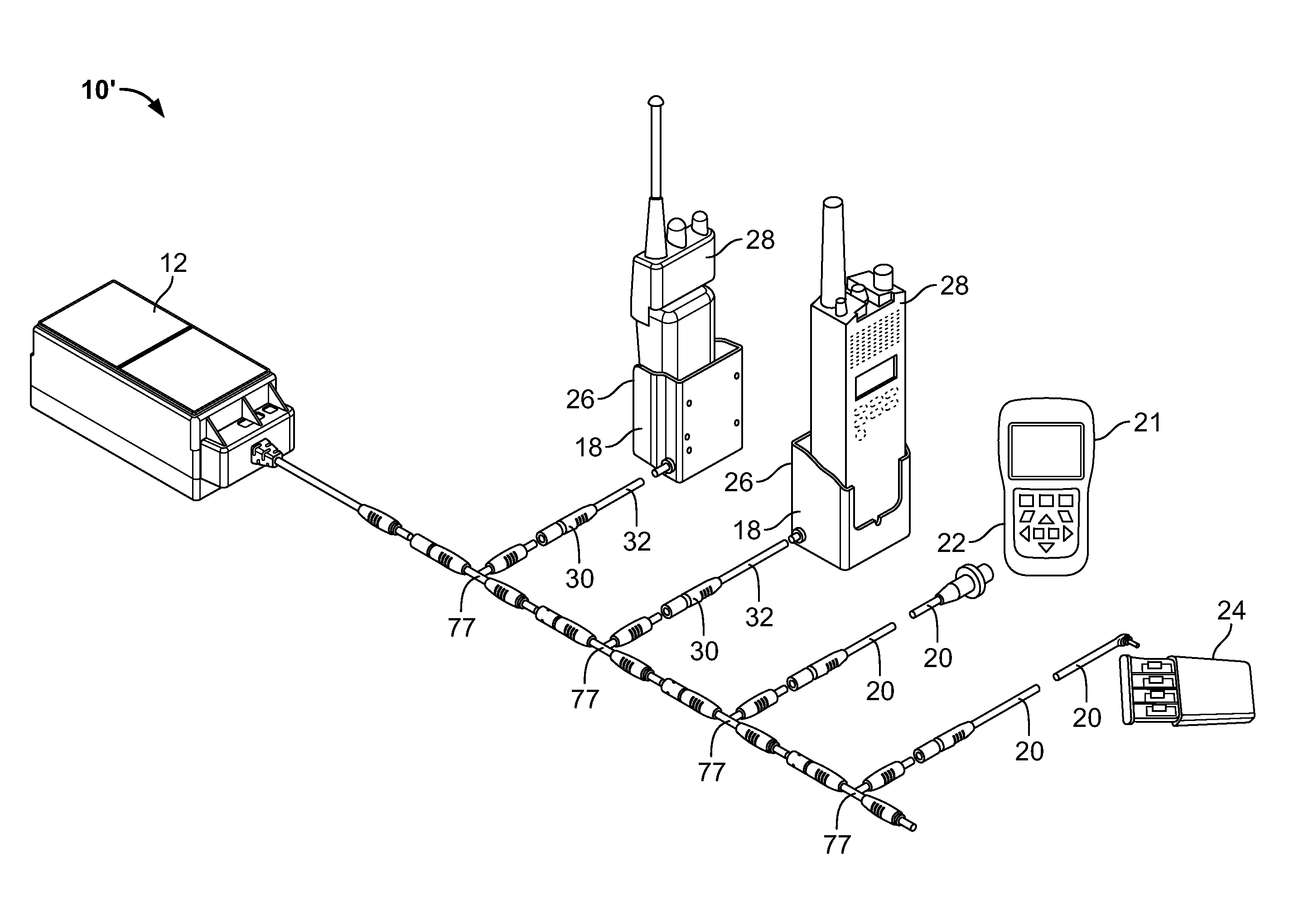
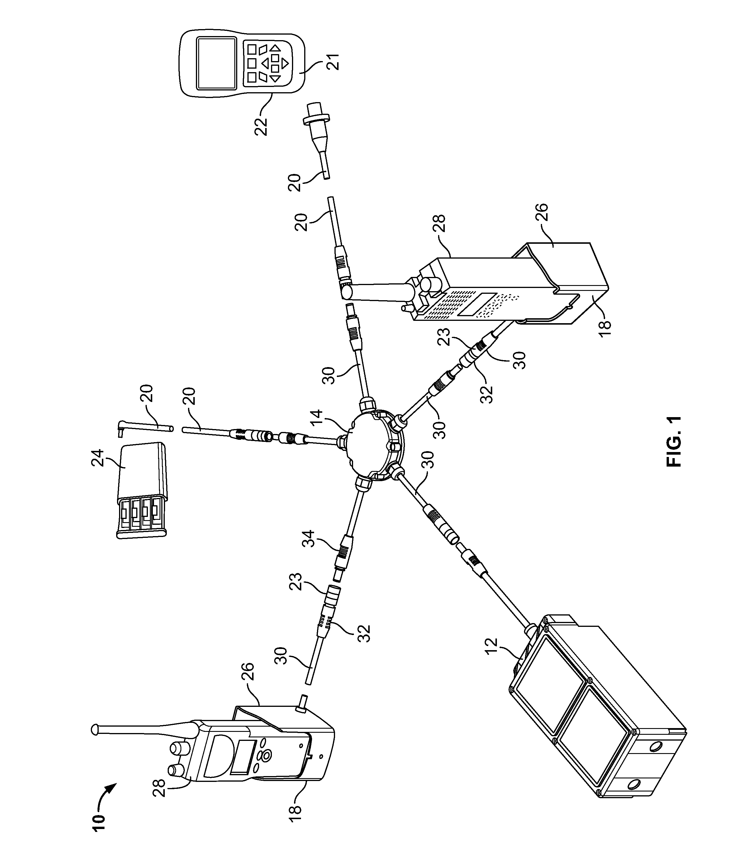
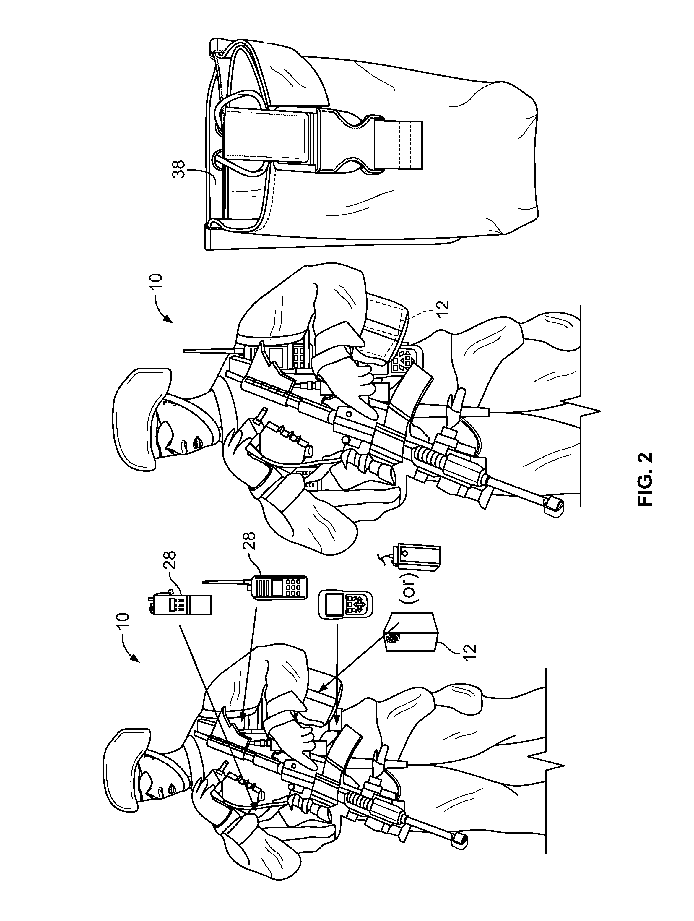
[0026]FIG. 1 is an exploded view of the components of a portable multiple battery rapid charging system 10, according to an embodiment of the present invention. FIG. 2 shows the portable multiple battery rapid charging system 10 of FIG. 1 as it may be worn by a soldier on his body armor system. The system 10 includes a light weight power source 12, preferably, but not limited to, a high capacity charging battery, a multi-port power distribution hub 14 removably connectable to the power source 12, one or more chargers 18 removably connectable to the multi-port power distribution hub 14, and one or more cable adapters 20 removably connectable to the multi-port power distribution hub 14. The adapters 20 are configured to be removably connectable to a device 21 having a direct charging port 22, and / or to a removable battery pack 24, such as an AA-type battery pack. Each of the chargers 18 is configured to include variable-shaped housings 26 configured to conformally receive rechargeable...


PUM


Abstract

An apparatus for charging multiple rechargeable devices is disclosed. The apparatus includes a hub or multiple T-connectors connected between a power source, preferably a Zinc-air battery, and several chargers, the hub / T-connectors configured to provide electrical and mechanical connectivity between the power source and the chargers. The apparatus includes housings configured to encase the chargers and to conformally receive each of the corresponding devices containing rechargeable batteries. The apparatus further includes pouches configured to removably receive chargers, devices, and the power source. When the power source voltage falls below a certain threshold, then a charger associated with a device having the smallest difference between its rated voltage and its measured voltage discontinues charging before other chargers. The apparatus is wearable by a user.

Description

GOVERNMENT RIGHTS IN THIS INVENTION[0001]This invention was made with U.S. government support under Army contract number BAA W15P7T-07-R-P042. The U.S. government has certain rights in this invention.FIELD OF THE INVENTION[0002]The present invention relates generally to power systems, and more particularly, to a system and a method for continuously charging a plurality of original equipment manufacturer (OEM) batteries carried in equipment worn by a soldier on the battlefield.BACKGROUND OF THE INVENTION[0003]There has been a proliferation of electronic equipment employed in the battlefield. More particularly, a soldier carries a plurality of electronic devices that require battery power. These electronic devices may include one or more radios, a GPS receiver, a laser target designator, and a battlefield computer. Mission profiles have increased the number of handheld devices and the time that the devices need to operate. In certain conditions, a soldier may need to carry up to 72 ba...

Claims


Application Information

Patent Timeline
Patent Type & Authority Patents(United States)
IPC IPC(8): H02J7/04H02J7/00
CPCH02J7/0044H02J7/007H02J7/0013H02J2310/22
Inventor SASSEN, JONATHAN MARKNALL, JR., GROVER LELANDBADICHI, RONENJUBIN, JEFFREY NELSONRIVIN, ANATOLY
Owner ELECTRIC FUEL BATTERY
Learn More