Disparity cursors for measurement of 3D images

a cursor and image technology, applied in the field of video test and measurement instruments, can solve the problems of crude and easy to inaccurate errors, time-consuming, and headaches of viewers, and achieve the effect of making quick and easy disparity measurements

Inactive Publication Date: 2013-11-19
TEKTRONIX INC
View PDF6 Cites 5 Cited by
  • Summary
  • Abstract
  • Description
  • Claims
  • Application Information

AI Technical Summary

Benefits of technology

[0006]A test and measurement instrument according to an embodiment of the present invention provides a disparity cursor for making quick and easy disparity measurements. In operation, a user uses a sample cursor to specify a pixel of a first image and uses the disparity cursor to specify a pixel of a second image. The test and measurement instrument then automatically provides a measured disparity value based on the two pixels.

Problems solved by technology

Too much disparity can cause headaches or even make viewers ill.
While this approach is simple, it is also crude and prone to inaccuracies.
This approach is more accurate, however it is time consuming, and it requires that the user have explicit details of the video format.

Method used


Image

  • Disparity cursors for measurement of 3D images
  • Disparity cursors for measurement of 3D images
  • Disparity cursors for measurement of 3D images

Examples


Embodiment Construction

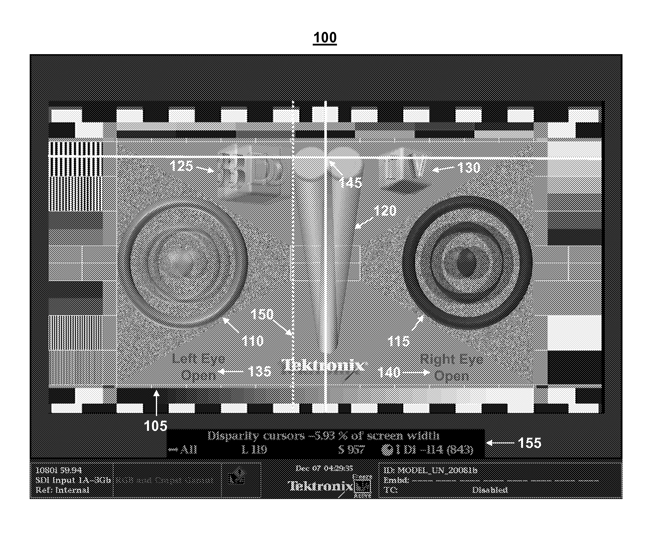
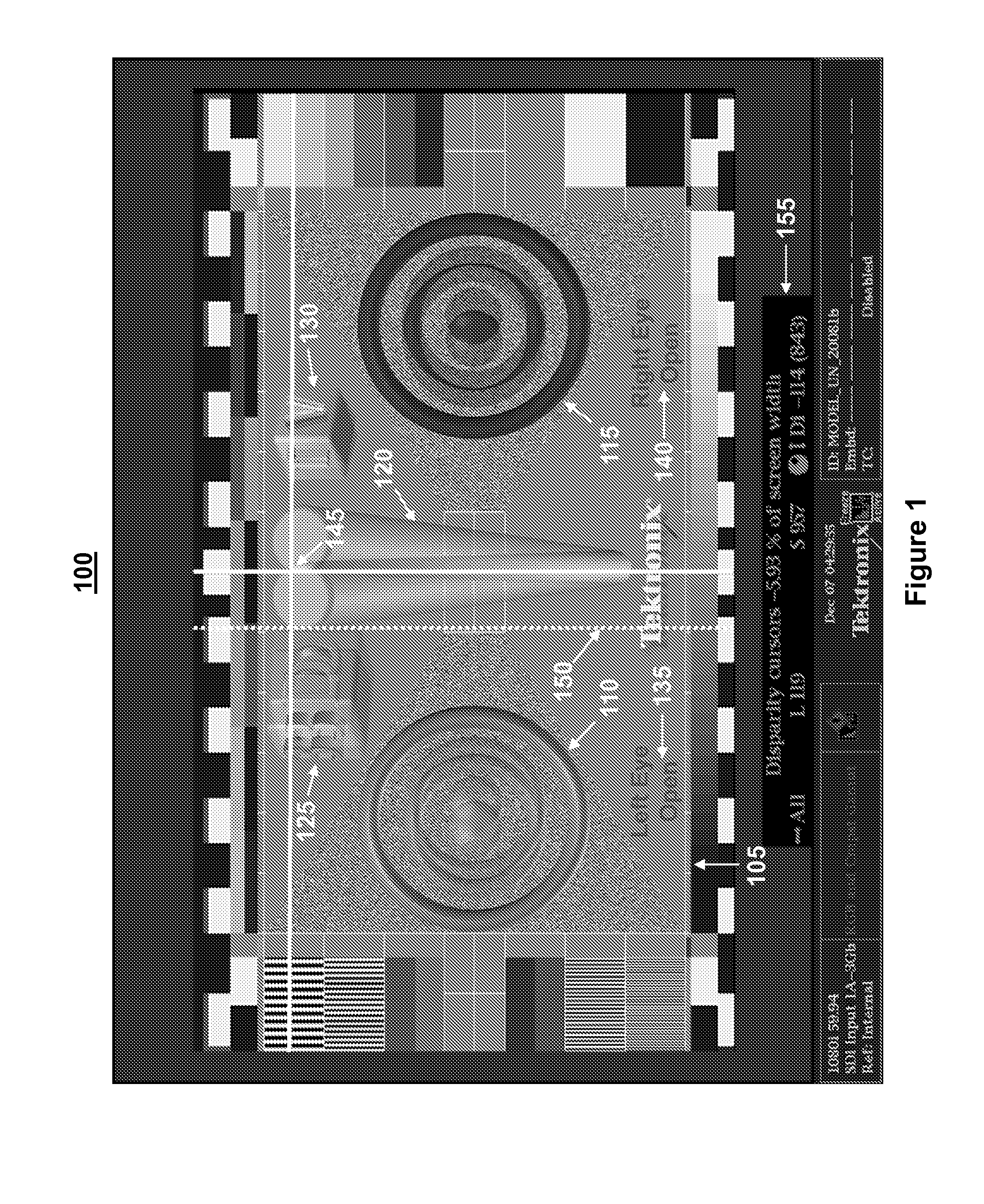
[0010]FIG. 1 depicts a display 100 of a video waveform monitor such as a WFM8000 Waveform Monitor available from Tektronix, Inc. of Beaverton, Oreg. The display 100 depicts an image under test, a conventional sample cursor 145, and a disparity cursor 150 according to an embodiment of the present invention, all of which are described in more detail below.

[0011]The image under test is a conventional test image that is commonly used for 3D testing. It is a composite image which consists of two separate 1080i images, a left-eye image and a right-eye image, each 1920×1080 active pixel picture area, which are superimposed into a single image. Both the left-eye and right-eye images contain some common elements in which the data is exactly the same. These common elements are located around the edge, and they are used for image registration, horizontal resolution, color bar, 4:3 safe area, and so on. The 3D content is located entirely within the center rectangle 105 and consists of a left bu...


PUM


Abstract

A test and measurement instrument according to an embodiment of the present invention provides a disparity cursor for making quick and easy disparity measurements. In operation, a user uses a sample cursor to specify a pixel of a first image and uses the disparity cursor to specify a pixel of a second image. The test and measurement instrument then automatically provides a measured disparity value based on the two pixels.

Description

CROSS-REFERENCE TO RELATED APPLICATIONS[0001]This application claims the benefit of U.S. Provisional Patent Application No. 61 / 426,894 titled “DISPARITY CURSORS FOR MEASUREMENT OF 3D IMAGES” filed on Dec. 23, 2010.FIELD OF THE INVENTION[0002]The present invention relates to video test and measurement instruments, and more particularly to disparity measurements for three dimensional (3D) images.BACKGROUND OF THE INVENTION[0003]In the production of 3D movies, disparity is the horizontal separation of the corresponding pixels of the left-eye view and the right-eye view of an object. The amount and polarity of disparity determines the depth of the object in the 3D plane, which causes the object to appear either close or far away relative to the normal image plane. If the disparity is negative, i.e., if the right-eye image is to the left of the left-eye image, then the disparate object appears closer than the normal image plane. If the disparity is positive, i.e., if the right-eye image ...

Claims


Application Information

Patent Timeline
Patent Type & Authority Patents(United States)
IPC IPC(8): G09G5/08
CPCH04N13/0425H04N17/00H04N13/327
Inventor DAVIES, ROBERT G.
Owner TEKTRONIX INC
Why Eureka
Try Eureka