Circuit breaker remote racking device

a circuit breaker and remote racking technology, applied in the direction of air-breaking switches, high-tension/heavy-dress switches, electrical apparatus, etc., can solve the problems of dangerous condition known as arc flash, short circuit of electric circuits, and inability to eliminate the risk of injury or death. ppe alone cannot solve the problem of short circuit,

Active Publication Date: 2013-12-10
INOLECT
View PDF7 Cites 6 Cited by
  • Summary
  • Abstract
  • Description
  • Claims
  • Application Information

AI Technical Summary

Benefits of technology

[0017]The sliding between supports is accomplished by placing wear resistant slippery nylon (not shown) in the area between the supports to eliminate contact friction. The nylon is located at the top of the stationary structural support, the bottom of the intermediate structural support, and along the entire length of the sliding motor structure. The stationary structural support, intermediate structural support, sliding motor structure, and motor mount structure are all made of extruded aluminum that is anodized for premier performance, quality, and corrosion resistance with a limited coefficient of friction.

Problems solved by technology

During these operations, electrical circuits may short-circuit and produce a dangerous condition known as an arc flash.
Arc-flash occurs when an electric current passes through air when insulation or isolation between electrified conductors is insufficient to withstand the applied voltage.
However, PPE alone will not eliminate the risk of injury or death because personnel are still in close proximity to the circuit breaker during racking operations.
U.S. Pat. No. 6,897,388attempts to address these issues, however, this reference and other references in the related art have not adequately solved the need for a simple and effective apparatus for remotely racking circuit breakers.

Method used


Image

  • Circuit breaker remote racking device
  • Circuit breaker remote racking device
  • Circuit breaker remote racking device

Examples


Embodiment Construction

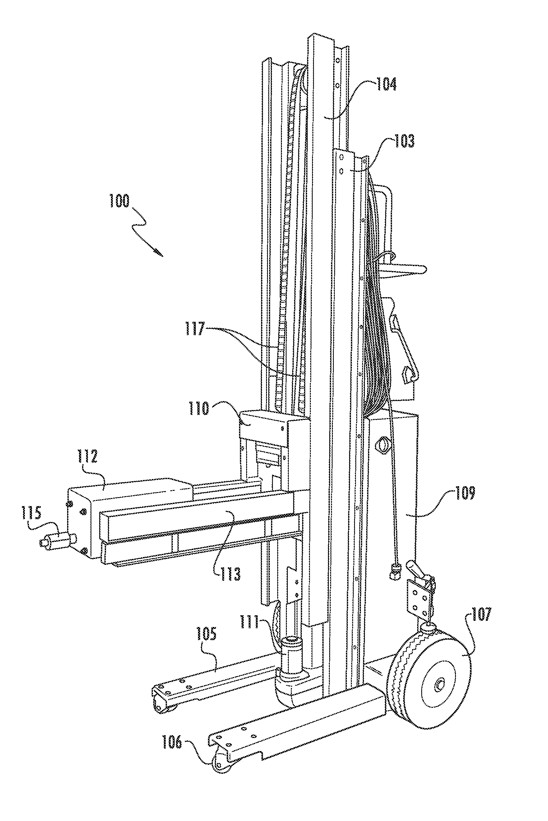
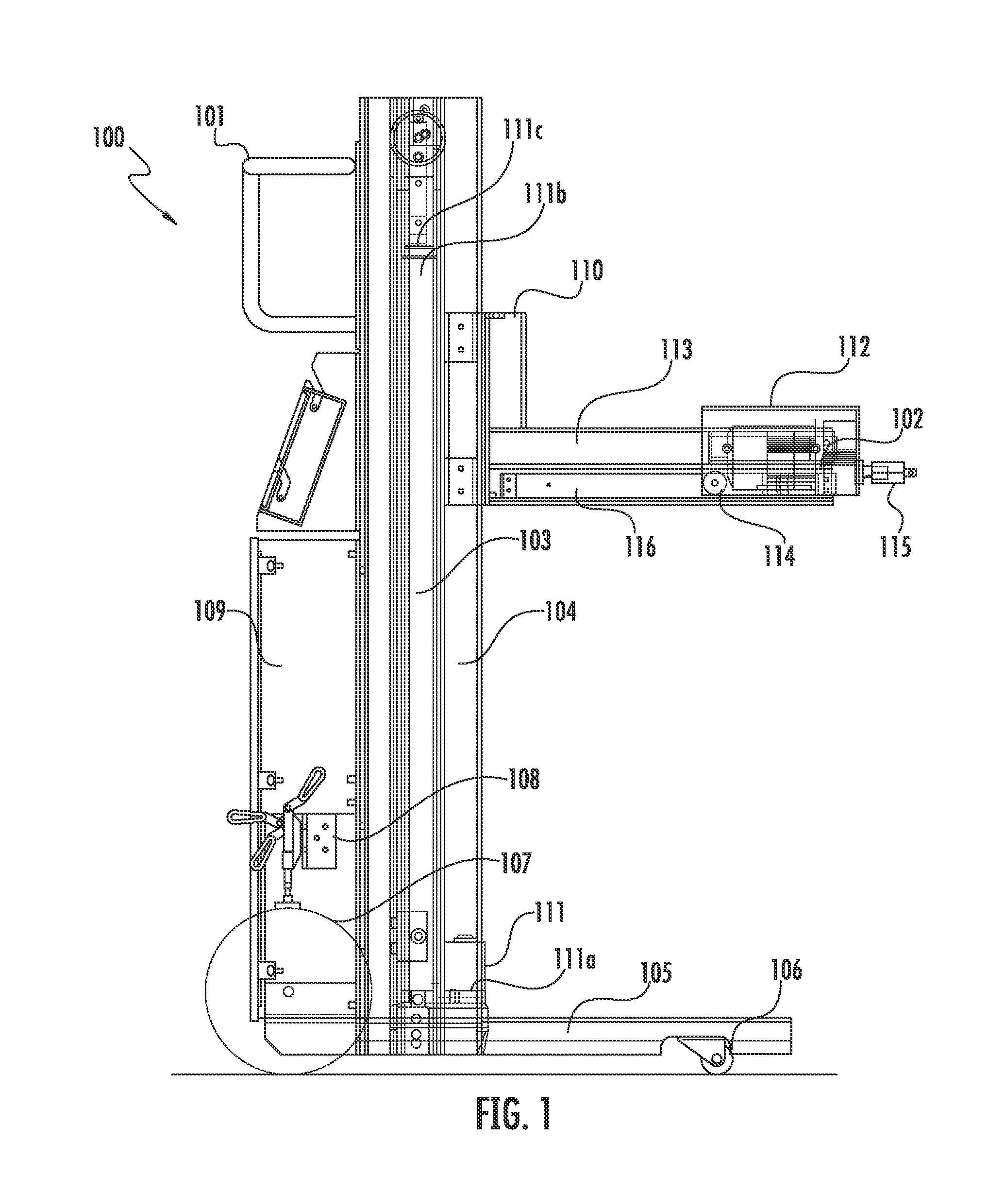
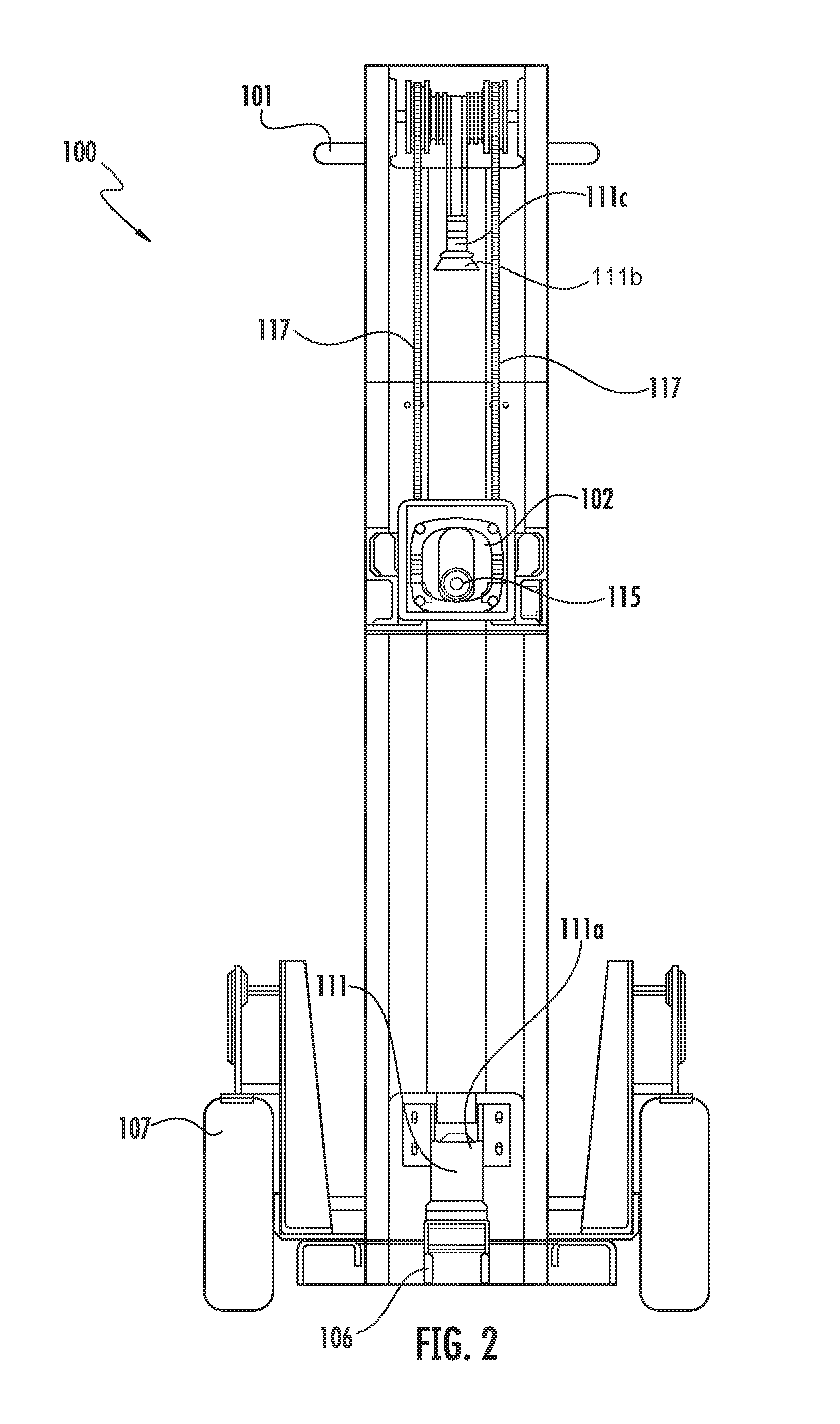
[0029]For purposes of illustration, the invention will be described as applied to low voltage circuit breakers. However, the invention may also be applied to other types of electrical apparatus (e.g., without limitation, circuit switching devices and other circuit interrupters such as contactors, motor starters, motor controllers and other load controllers) housed within a housing structure, such as a circuit breaker cell or switchgear cabinet.

[0030]Directional phrases used herein relate to the orientation of the elements shown in the drawings and are not limiting upon the claims unless expressly recited therein. For example, left, right, top, bottom, clockwise, counterclockwise and derivatives thereof.

[0031]As employed herein, the term “fastener” refers to any suitable connecting, coupling, or tightening mechanism expressly including, but not limited to, screws, bolts, pins, and the combinations of bolts and nuts (e.g., without limitation, lock nuts) and bolts, washers and nuts.

[00...


PUM


Abstract

A device is provided for remotely racking circuit breakers and contactors that are housed within a housing structure, such as a circuit breaker cell or switchgear cabinet.

Description

CROSS-REFERENCE TO RELATED APPLICATION[0001]This application claims benefit to provisional application 61 / 379,846 filed on Sep. 3, 2010.STATEMENT REGARDING FEDERALLY SPONSORED RESEARCH OR DEVELOPMENT[0002]Not Applicable.THE NAMES OF THE PARTIES TO A JOINT RESEARCH AGREEMENT[0003]Not Applicable.INCORPORATION-BY-REFERENCE OF MATERIAL SUBMITTED ON A COMPACT DISC[0004]Not Applicable.BACKGROUND OF THE INVENTION[0005]1. Field of the Invention[0006]The present disclosure relates to subject matter for remotely racking a circuit breaker, particularly subject matter including a force amplifying or levering mechanism for locking the breaker in each of its plurality of positions automatically without the need for operator intervention to determine how far the circuit breaker must be displaced to place it in the desired position.[0007]2. Description of Related Art[0008]In utility and industrial applications, circuit breakers and contractors are utilized to establish electrical circuits. From tim...

Claims


Application Information

Patent Timeline
Patent Type & Authority Patents(United States)
IPC IPC(8): H01H9/20
CPCH02B3/00H02B11/02
Inventor GREER, CHESTER LEVINORTON, JOSHUA ALLEN
Owner INOLECT
Why Eureka
Try Eureka