Machine for bending a profile in two bending directions and bending tool

Active Publication Date: 2013-12-31
EATON LEONARD EURO
View PDF25 Cites 5 Cited by
  • Summary
  • Abstract
  • Description
  • Claims
  • Application Information

AI Technical Summary

Benefits of technology

The patent text describes a bending machine that has rules arranged in a single carriage, which simplifies the machine significantly. By using a single guide and feed control system, the machine can bend in two directions, which is currently possible only with machines that have two guides and two control systems. This simplifies the movement of the profiles and the changes in bending direction, as only one movement is required along an axis perpendicular to the long axis of the machine. This allows for easier and more efficient use of the bending machine.

Problems solved by technology

On the other hand, this kinematic leads to the production of relatively complex bending heads that furthermore have a relatively large overall size.
Moreover, an additional disadvantage of such bending machines is that the bending angle is limited to 180°, or less than 180° if the end of the bent length carries an item such as a nut to enable disengagement of the profile after bending.
On the other hand, the major drawback of such bending machines is that they enable bending in only one bending direction.

Method used


Image

  • Machine for bending a profile in two bending directions and bending tool
  • Machine for bending a profile in two bending directions and bending tool
  • Machine for bending a profile in two bending directions and bending tool

Examples


first embodiment

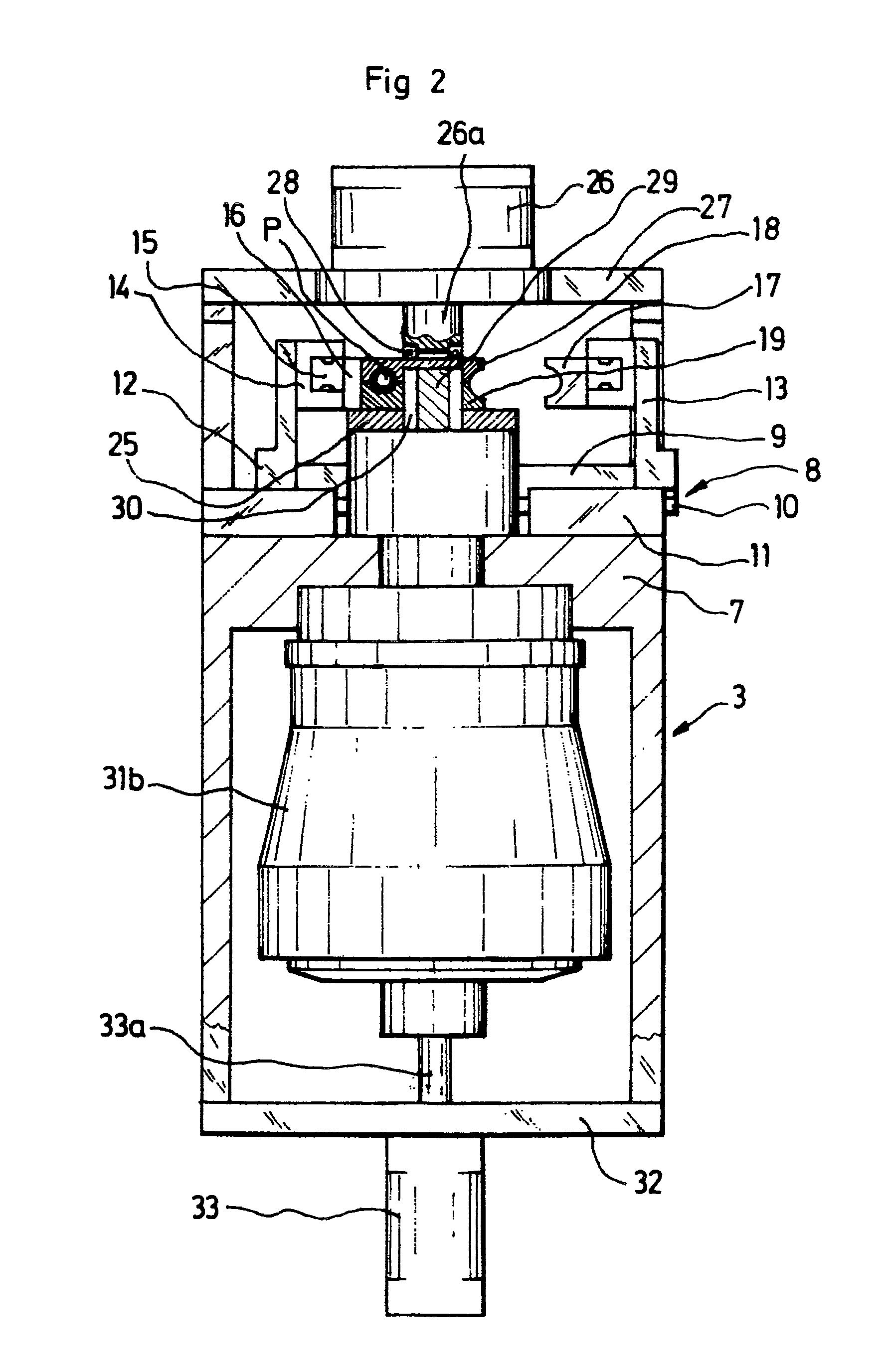
[0076]Moreover, the rotary shaft 29 is constrained to move in translation with the vertical rod 33a of an actuator 33 the body of which is disposed on the lower table 32 of the first carriage 3, said actuator being adapted:[0077]in its deployed position, to hold the rotary shaft 29 engaged with the two clamping forms 18, 19 in each of the relative positions of said clamping forms, and notably its joined and spaced-apart extreme positions, represented in FIGS. 2 and 3a, and[0078]in its retracted position, and in the spaced-apart position of the two clamping forms 18, 19, to enable the rotary shaft 29 to be placed in a retracted position in which, as shown in FIG. 3b, said rotary shaft frees a space between the two junction faces 18a, 19a of said clamping forms adapted to allow the passage of the profile P for changing the bending direction. FIG. 4 is a perspective view of the

[0079]According to this principle, the rotary shaft 29 has the function of indexing the relative position in ...

second embodiment

[0105]Note further that in this second embodiment the change of bending direction is effected by virtue of the facility for movement of the tool relative to the profile P along the axes Y and Z.

[0106]FIG. 8 shows a variant of this second embodiment in which, firstly, the third carriage 51 carries a single vertical plate 80 the upper end of which forms a horizontal rail 84 extending along the axis X.

[0107]Moreover, in this variant the two rules are produced from a single rectangular parallelepiped-shaped block 81 machined to have:[0108]in planes parallel to the plane (X, Z), two opposite vertical faces 82, 83 in each of which are formed two superposed grooves 82a-82b, 83a-83b, respectively, with different sections, adapted to house profiles with different sections, and[0109]a lower face in which is produced a slide 85 adapted to house the rail 84.

[0110]In this variant, the rules 82, 83 are produced in a single block 81 carried by a single carriage 80 the movement of which requires on...


PUM

PropertyMeasurementUnit
Angleaaaaaaaaaa
Angleaaaaaaaaaa
Lengthaaaaaaaaaa

Abstract

The invention relates to a machine for bending a profile in two bending directions, that comprises a bending tool including at least two clamping forms (19) centered on the profile bending axis and having the shape of disks having planar junction surfaces (19a) extending in planes perpendicular to said bending axis, in which are formed two rectilinear grooves (20b, 21b) and a peripheral rebate (22b) extending between said grooves and profiled as a continuation thereof, the grooves and the rebate being adapted so that, in the joined position of the junction surfaces (19a) of two clamping foams, the joined grooves define two clamping ducts of a profile and the joined rebates define a profile-winding bearing surface extending between said clamping ducts.

Description

FIELD OF THE INVENTION[0001]The invention concerns a machine for bending a profile in two bending directions and is also directed to a bending tool for such a bending machine.DESCRIPTION OF RELATED ART[0002]At present standard bending machines comprise means for holding profiles and moving them along a longitudinal axis (x) and a bending head rotatable about a bending axis (z), said bending head including as standard a bending roller and a clamping jaw having bearing surfaces between which a profile to be bent passes, is clamped and then bent:[0003]the bending roller axis coinciding with the bending axis (z), and[0004]the clamping jaw being mobile in translation relative to the bending roller along an axis perpendicular to the bending axis (z) between a position joined with said bending roller for clamping and bending a profile to be bent and a position spaced from said bending roller for introducing a profile to be bent between the latter and said clamping jaw.[0005]Such machines h...

Claims


Application Information

Patent Timeline
IPC IPC(8): B21D7/04
CPCB21D7/021B21D7/024
Inventor JAUBERT, PHILIPPEDUNAND, NICOLAS
Owner EATON LEONARD EURO
Why Eureka
Try Eureka