Rotary cutting tool

a cutting tool and rotary technology, applied in the field of chucks, can solve the problems of limited depth of depression, and achieve the effects of reducing the force required for turning the wrench, and reducing the depth of depression

Inactive Publication Date: 2013-12-31
ISCAR LTD
View PDF10 Cites 4 Cited by
  • Summary
  • Abstract
  • Description
  • Claims
  • Application Information

AI Technical Summary

Benefits of technology

[0019]The present invention has the preferred advantages as to a firm securing without any additional locking means. Preferably it allows a tighter locking without the risk of sliding out from the securing position, neither forward nor backward.
[0020]In accordance with the present invention, the contoured clamping surface faces radially inwardly, wherein the contoured clamping surface of the aforementioned prior art faces radially outwardly. As a consequence, an internal grinding for creating the contoured clamping surface can be used, wherein an external grinding is used in the prior art. A significant smaller diameter grinding stone can be used for an internal grinding, which provides the advantage of creating a deeper trough, resulting in a higher stop ridge. A higher stop ridge ensures complete blocking of the roller, since the roller can not pass over the high stop ridge. A further turn of a wrench brings the roller closer to the stop ridge, resulting in tougher locking forces. By virtue of the tough locking forces, the force required for turning the wrench is minimal, and can be even done as a manual process. After the primary locking, as the article is secured forcibly, it turns into an integral part of the chuck.
[0021]Further or additional preferred advantages of the present invention are obvious from the general discussion above as well as the detailed discussion of preferred embodiments as provided below. In particular, the present invention prevents risks of undesired release of the cutting tool or the work-piece secured in the chuck by an improved securing mechanism.

Problems solved by technology

Nevertheless, the depth of the depression is limited, and a further turn of a wrench results in sliding out from the depression, therefore sliding out from the securing position.

Method used


Image

  • Rotary cutting tool
  • Rotary cutting tool
  • Rotary cutting tool

Examples


first embodiment

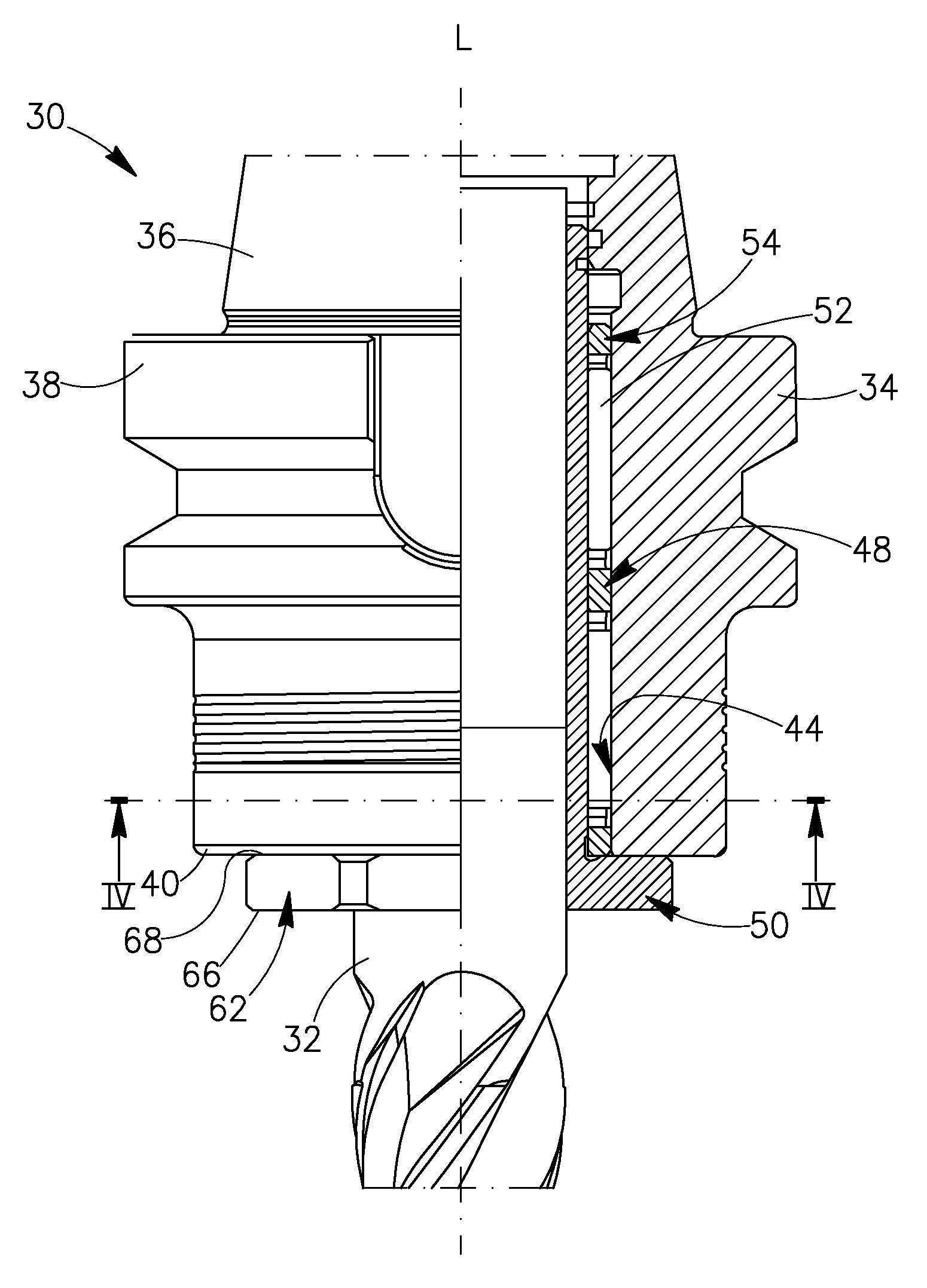
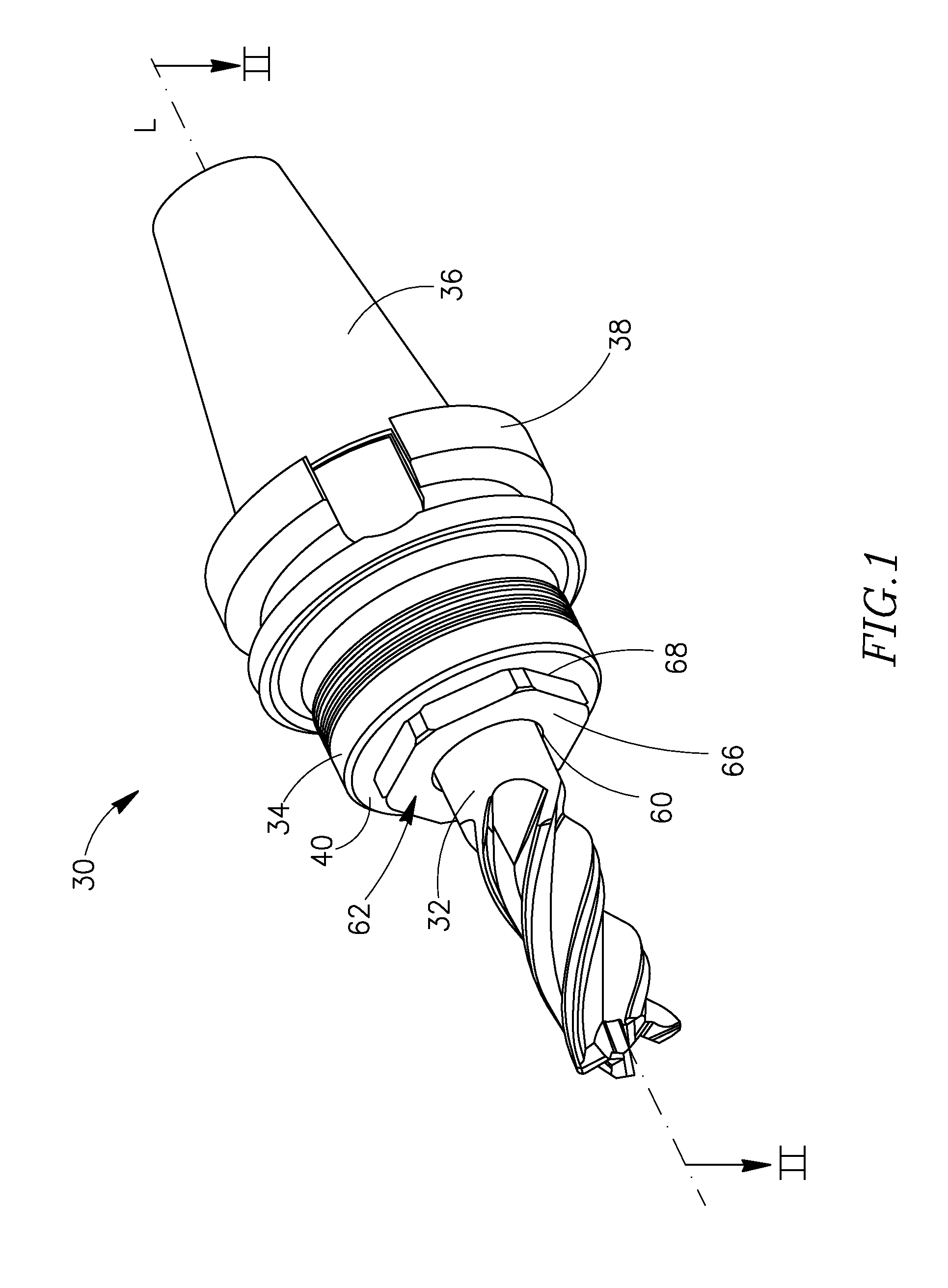
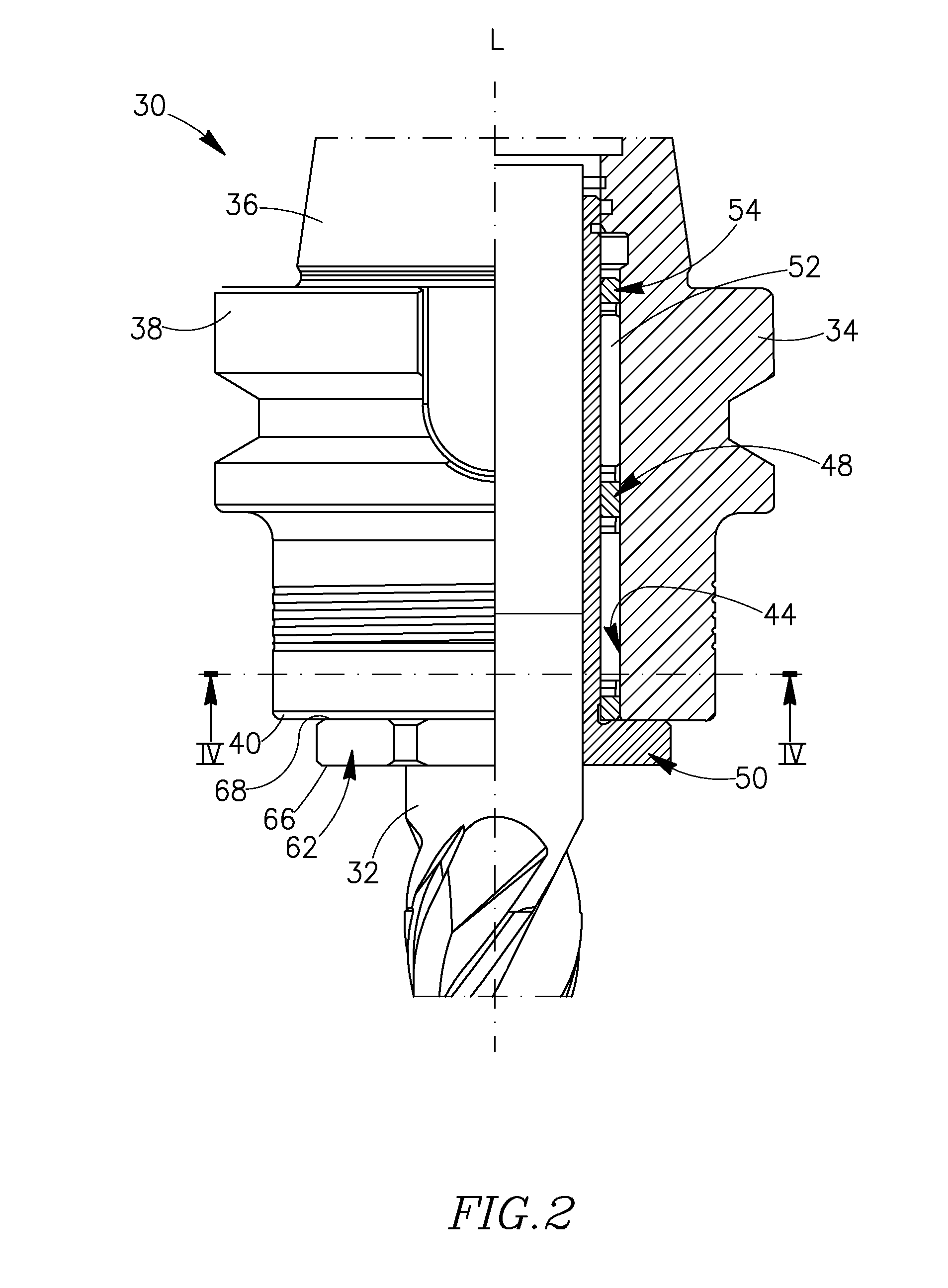
[0035]Attention is drawn to FIGS. 1 to 5. In accordance with a first embodiment, a chuck 30 releasably secures a tool shank 32 of a cutting tool in an integrally-formed chuck receiving portion 34 thereof. The cutting tool may be a rotary cutting tool, such as an end mill, though the shank may belong to some other type of tool, or even be a work piece.

[0036]The chuck 30 has a longitudinal axis L defining a front-to-rear direction, and also has an integrally-formed rear mounting portion 36 which is releasably mountable in a rotary machining tool (not shown). The mounting portion 36 extends forwardly to an integrally formed mounting flange 38, with the chuck receiving portion 34 extending forwardly from the mounting flange 38 to a receiving front face 40 which is perpendicular to the longitudinal axis L. The exact shape and operation of the mounting portion 36 and the mounting flange 38 are generally known to those skilled in the art.

[0037]A receiving bore 42 has a contoured clamping s...

second embodiment

[0052]The clamping through-hole 260 has a tool shank 232 received therein. A plurality of rollers is accommodated at spaced apart intervals between the sleeve body 264 and the contoured clamping surface 244 of the receiving bore 242. However, chuck 230 has a single roller 252A, 252B, 252C, etc. associated with each clamping segment 282 while chuck 30 has a roller trio 98 of identical first, second and third rollers 52′, 52″ and 52′″ associated with each clamping segment 82. Accordingly the clamping mechanism 248 in this second embodiment, as presented in FIGS. 11 and 12, has a total of three such rollers.

[0053]In a releasing position of the chuck 230, shown in FIG. 11, the roller 252A associated with the clamping segment 282 is located at a trough 286 of the clamping segment 282, facilitating free insertion, positioning, or removal of the tool shank 232 relative to the clamping through-bore 260. Rotating the clamping sleeve 250 towards a securing position causes the roller 252A asso...


PUM


Abstract

A chuck for clamping an article has a receiving portion including a receiving bore having a longitudinal axis L, and a radially inwardly facing contoured clamping and receiving inner surface. A clamping sleeve is accommodated in the receiving bore and is rotatable between a releasing position and a securing position. The contoured clamping and receiving surface has one or more clamping segments, each clamping segment having a ramp between a trough and a crest, a second ramp between the crest and a depression, and a third ramp between the depression and the succeeding stop ridge. Rotating the clamping sleeve within the receiving bore causes one or more rollers associated with each clamping segment to cooperate with the contoured clamping surface to effect the releasing and the securing of the article.

Description

FIELD OF THE INVENTION[0001]The present invention disclosure relates to a chuck, and particularly to chucks used for releasably securing cutting tools or work-pieces to machining tools.BACKGROUND OF THE INVENTION[0002]Chucks are used to removably secure cutting tools or work-pieces to machining tools, such as metal cutting machines. As is well known in the art, chucks generally have a mounting portion which is adapted to be releasably clamped in the machining tool, and a receiving portion which releasably holds a cutting tool or a work-piece.[0003]U.S. Pat. No. 2,039,149 to Dodge discloses a one way clutch (an over-running, or a free-wheeling clutch) coupling a driving element to a driven element, employing rollers relieved from sliding or rolling loads, having very little back-lash which is further cushioned by an oil film. The over-running clutch includes inner and outer members, a series of wedge blocks each having on one side a cylindrical surface adapted to be forced into frict...

Claims


Application Information

Patent Timeline
Patent Type & Authority Patents(United States)
IPC IPC(8): B23B31/117
CPCB23B31/1177B23B2260/116Y10T279/17965Y10T279/17B23B31/10B23B31/117B23Q3/06
Inventor GUY, HANOCH
Owner ISCAR LTD
Why Eureka
Try Eureka