Method and apparatus for analog pulse pile-up rejection

a technology of pileup and analog pulse, applied in the field of sensors, can solve the problems of spectral measurement distortion, spectral measurement distortion, and limitation of the detection of spectral lines with amplitudes, and achieve the effect of reducing the detection cos

Active Publication Date: 2013-12-31
BROOKHAVEN SCI ASSOCS
View PDF9 Cites 15 Cited by
  • Summary
  • Abstract
  • Description
  • Claims
  • Application Information

AI Technical Summary

Problems solved by technology

Such pile-up generates distortion in the spectrum of a measured source due to pulse amplitudes arising from pile-up.
It is further noted that the distribution function indicates that as rate increases the probability of a short interval between events increases and pile-up occurs, with pile-up causing one or more peak detectors to measure one or more amplitudes higher than desired, such measurement generating spectral measurement distortion.
The spectral measurement distortion limits the detection of spectral lines with amplitudes higher than the lines at a high rate.
Attempts to address pile-up of detected pulses have been made with limited success.
The power needed to perform ADC in each channel and the time needed for digital processing are prohibitive for at least those applications that require high density of channels or that have a limited power budget.

Method used


Image

  • Method and apparatus for analog pulse pile-up rejection
  • Method and apparatus for analog pulse pile-up rejection
  • Method and apparatus for analog pulse pile-up rejection

Examples


Embodiment Construction

[0044]The present pile-up handling detects and rejects those amplitudes characterized by pile-up in order to recover sensitivity at higher amplitude. Moreover, the pile-up handling of the present invention provides efficient pile-up rejection, minimized dead time, power savings, time savings, and increased sensitivity to low amplitude signals compared to conventional pile-up handlers.

Pile-Up Handling Operations

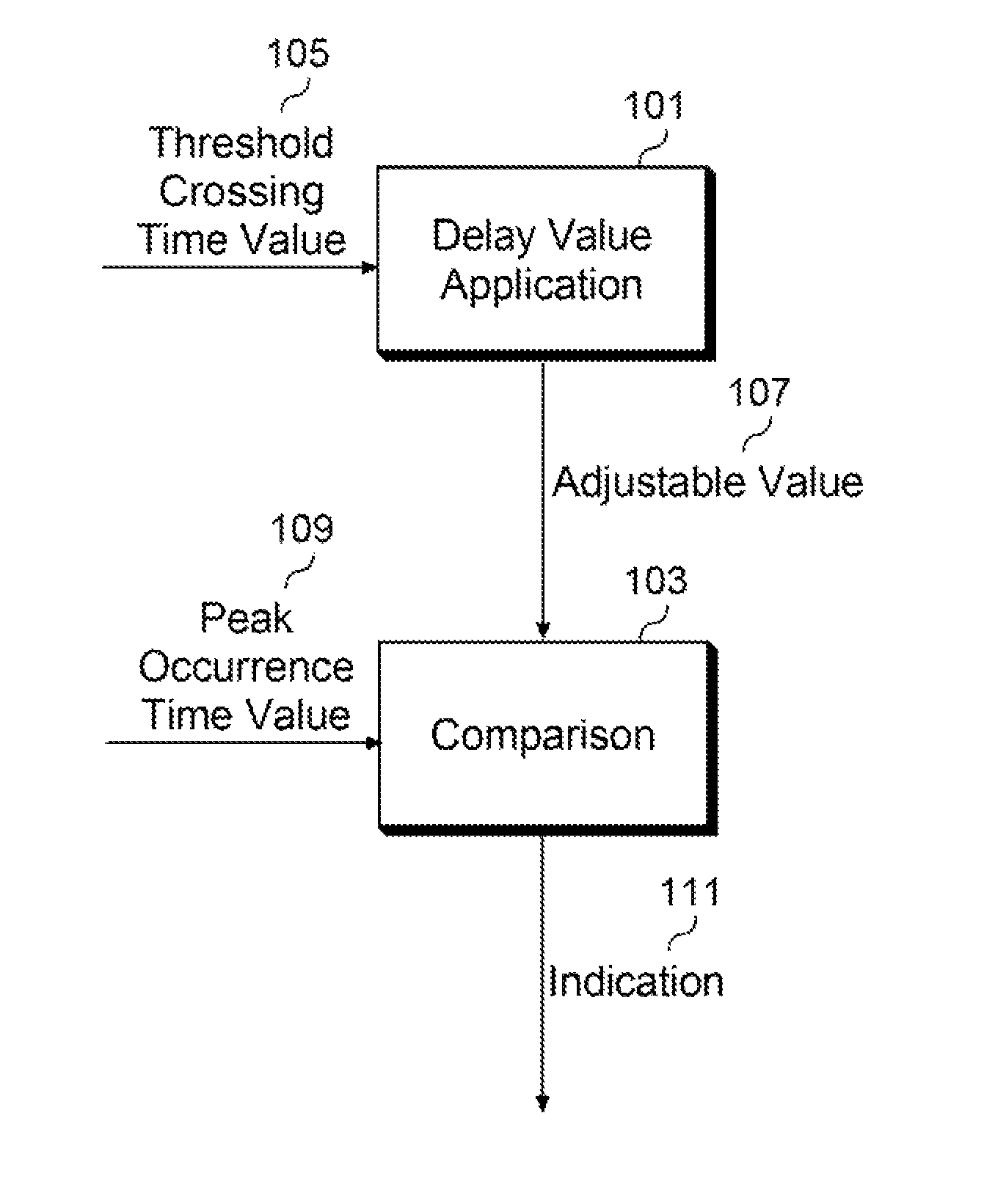
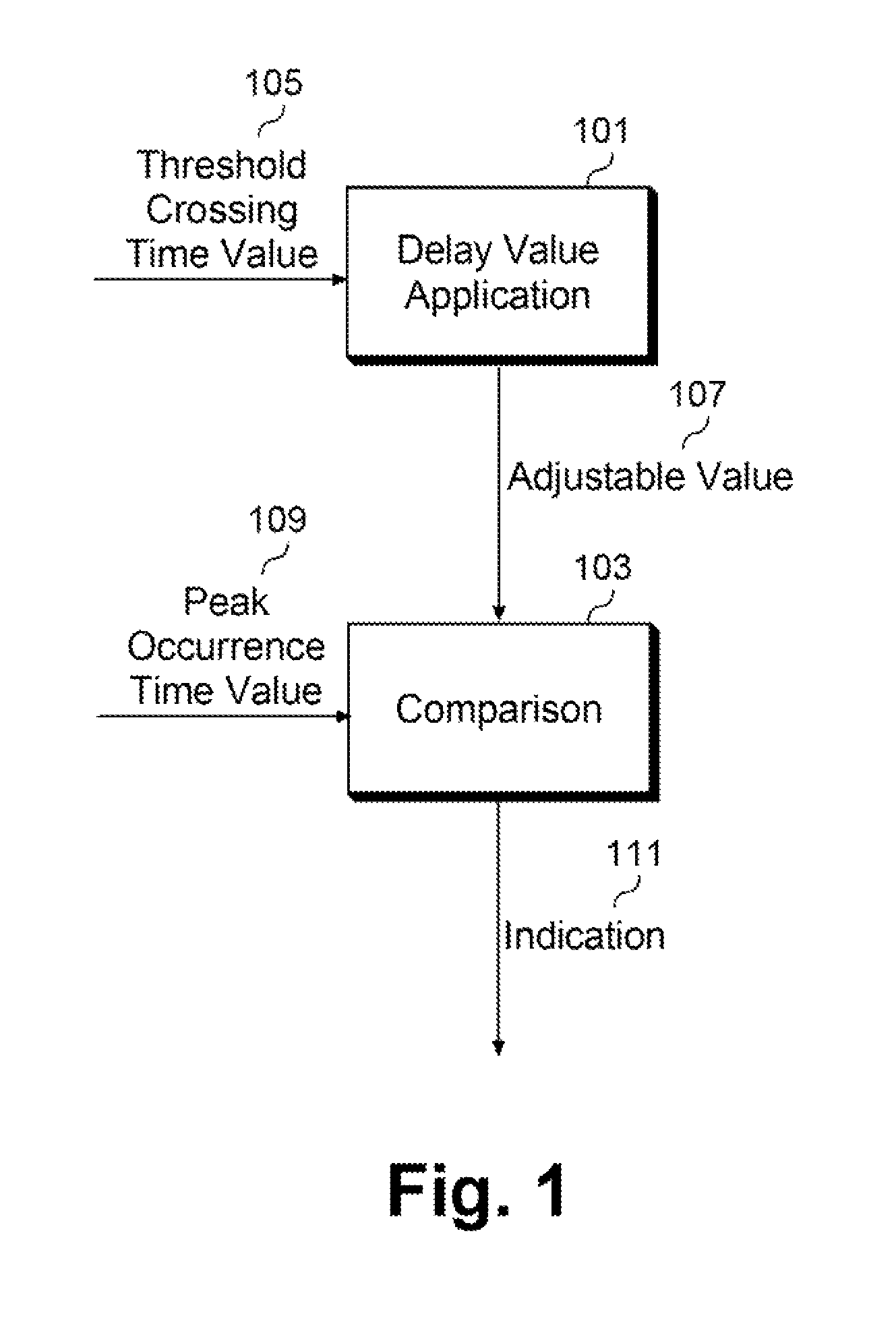
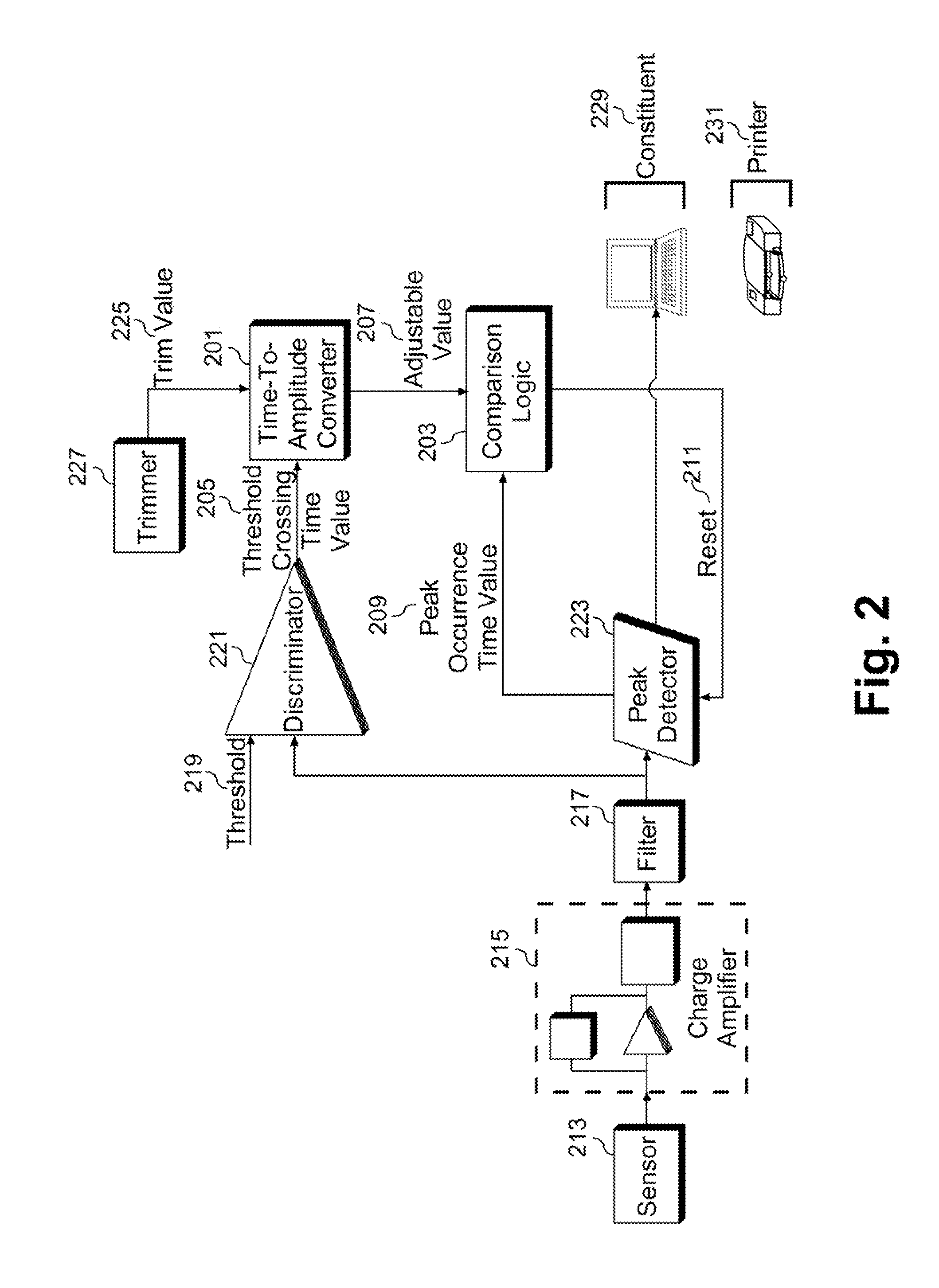
[0045]Pile-up handling operations that address distortion due to pile-up in detected signals are disclosed. The pile-up handling operations include receiving a threshold-crossing time value and a peak occurrence time value for each peak detected in a receive signal. The pile-up handling operations further include comparing the peak occurrence time value with an adjustable value. As one example, the pile-up handling operations include determining if the peak occurrence time value is greater than the adjustable value. Alternately or additionally, the pile-up handling operations ...


PUM


Abstract

A method and apparatus for pulse pile-up rejection are disclosed. The apparatus comprises a delay value application constituent configured to receive a threshold-crossing time value, and provide an adjustable value according to a delay value and the threshold-crossing time value; and a comparison constituent configured to receive a peak-occurrence time value and the adjustable value, compare the peak-occurrence time value with the adjustable value, indicate pulse acceptance if the peak-occurrence time value is less than or equal to the adjustable value, and indicate pulse rejection if the peak-occurrence time value is greater than the adjustable value.

Description

CROSS REFERENCE TO RELATED APPLICATIONS[0001]This application claims the benefit of U.S. Provisional Application No. 61 / 330,437, filed on May 3, 2010, the content of which is incorporated herein in its entirety.STATEMENT OF GOVERNMENT RIGHTS[0002]This invention was made with Government support under contract number DE-ACO2-98CH10886, awarded by the U.S. Department of Energy. The Government has certain rights in the invention.BACKGROUND[0003]I. Field of the Invention[0004]This invention relates generally to the field of sensors. In particular, the present invention applies to electronic systems that measure amplitudes of randomly arriving pulses, such as systems for in charge amplification and processing of signals from sensors.[0005]II. Background of the Related Art[0006]Detection is an established technique in the fields of nuclear medicine and astrophysics. In recent years, the use of detectors to image and characterize known as well as unknown sources has been advantageously appl...

Claims


Application Information

Patent Timeline
Patent Type & Authority Patents(United States)
IPC IPC(8): G01T1/17
CPCG01T1/171H03K5/1532
Inventor DE, GERONIMO, GIANLUIGI
Owner BROOKHAVEN SCI ASSOCS
Why Eureka
Try Eureka