LED tube and lamp arrangement

a technology of led tubes and lamps, applied in the field of lamps, can solve the problems of deteriorating electric safety, not meeting electric safety requirements, and not being able to touch any parts at the mains voltage, and achieve the effect of avoiding stray capacitance caused by the control conductor

Active Publication Date: 2014-01-07
TEKNOWARE
View PDF17 Cites 12 Cited by
  • Summary
  • Abstract
  • Description
  • Claims
  • Application Information

AI Technical Summary

Benefits of technology

[0033]The embodiments of the invention help prevent a situation where only one end of the LED tube is connected to the live parts of the lighting fixture and where the person mounting the tube lamp may obtain an electric shock through the LED tube from the yet unmounted end. The optical signal line(s) according to the embodiments of the invention reduce or prevent stray capacitance from the measuring and / or control conductors running inside the LED tube and connected to the safety unit to the touchable metal parts, such as the cooling element, of the LED tube. This further reduces the risk of an electric shock during installation.
[0035]In the embodiments of the invention to which cross-connection of control is applied, detection of voltage at one (“hot”) end of a LED tube results in the connection of the dead (“cold”) end to the LED circuitry. The dead LED circuitry then does not cause stray capacitance and leakage current to the metal parts or body of the tube lamp. The LED circuitry becomes live only after both ends of the LED tube have been mounted on the lighting fixture, i.e., when the second “cold” end also becomes live (“hot”). When the cross-connected control signals are transferred optically, the stray capacitance caused by the control conductors is also avoided.

Problems solved by technology

According to the safety regulations in the field of electricity, lighting fixtures are to be constructed in such a way that, when a fluorescent tube is replaced, it is not possible for a user to touch any parts at the mains voltage even if the lighting fixture were carrying voltage.
With LED tubes, this electric safety requirement is not met.
Another factor deteriorating electric safety is the cooling of a LED tube.
A problem with these cooling solutions using metal is that the metallic cooling part must be insulated sufficiently reliably from the LED circuits.
If such LED tubes with a metallic cooling part are used such that they are fed by an electronic ballast, a high frequency, in particular, causes a further problem.
This leakage current may cause the risk of an electric shock which may even be life-threatening.

Method used


Image

  • LED tube and lamp arrangement
  • LED tube and lamp arrangement
  • LED tube and lamp arrangement

Examples


Embodiment Construction

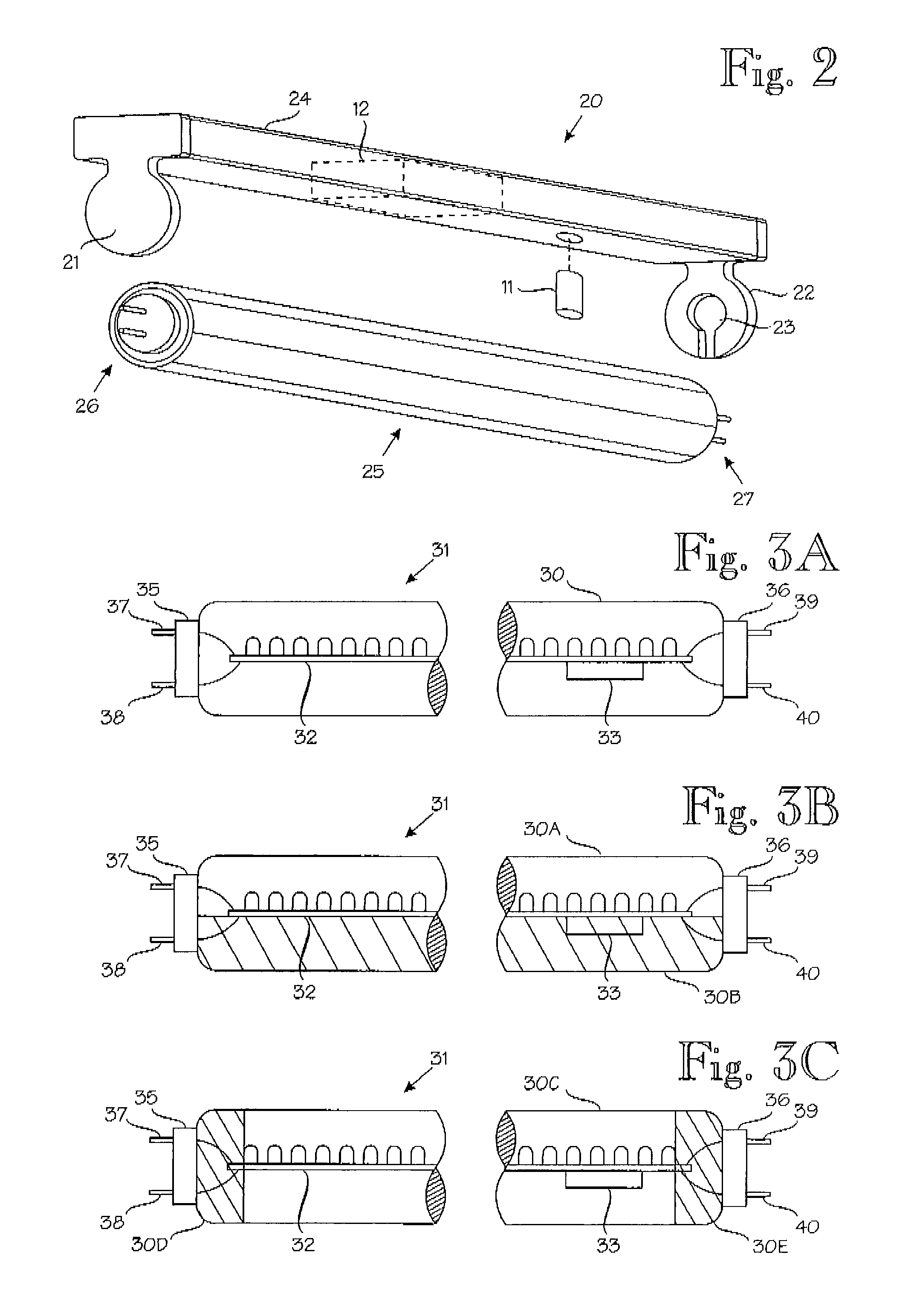
[0048]The area of application of the invention encompasses all lamps, particularly tube lamps which have one or more LEDs as the light source and with which a fluorescent tube lighting fixture or the like can be replaced.

[0049]FIG. 3A illustrates a simplified example of a potential structure of a LED tube. The lamp 31 consists of a straight (or bent) tube 30 which is of suitable translucent material, such as glass or plastic, or possibly of fluorescent material. The tube 30 does not have to be air-tight. On the contrary, there may be openings, holes, and / or slots for providing air circulation and cooling (e.g. U.S. Pat. No. 7,611,260), whereby the air flows through these holes and transfers heat out of the LEDS outside the tube. In such a solution, owing to the LED tube body made of plastic or other insulation material, high insulation level of the live parts is still maintained.

[0050]Alternatively, part of the tube coating of the LED tube may be made of metal or comprise a metal st...


PUM


Abstract

A LED tube includes a translucent or fluorescent tube of substantially the shape and size of a fluorescence tube, inside which one or more LED components and a current control unit are installed. At both ends of the LED tube, there is a pair of contact pins for connecting the light element mechanically and electrically to the tube holders of the fluorescence tube lighting fixture. The tube lamp has a safety unit arranged to prevent a voltage from transferring through the tube lamp from its one end to the other until a voltage supplied from the corresponding tube holder of the lighting fixture to the pair of contact pins has been separately detected at each end of the tube lamp. Inside the LED tube, there is at least one optical line that is arranged to transfer a control or measurement signal associated with the safety unit from one end of the LED tube to the other without capacitive leakage currents.

Description

BACKGROUND OF THE INVENTION[0001]The invention relates to lamps and, in particular, to LED tubes which have one or more LEDs as light sources and which can replace a fluorescent tube.[0002]Fluorescent lamps are widely used in different objects, such as in homes, offices and industry. Fluorescent lamps are more durable, economical and efficient than incandescent lamps, in which most of the electric power turns into heat instead of light. In a traditional fluorescent lamp, the body is a straight tube with a length of 15 to 60 times the diameter of the tube. The tube may also be bent, in which case it may be of almost any shape. Fluorescent tubes are low-pressure mercury discharge lamps in which the inner surface of the tube is coated with fluorescent material. The structure of a fluorescent tube is very simple and is illustrated in FIG. 1A. The lamp consists of an air-tight glass tube 4 containing a small amount of mercury, an inert gas, a fluorescent coating (luminophor), such as pho...

Claims


Application Information

Patent Timeline
Patent Type & Authority Patents(United States)
IPC IPC(8): H05B37/02H05B44/00
CPCY02B20/386Y02B20/383H05B33/0806H05B33/0884H05B33/0803F21K9/17F21Y2101/02F21Y2103/003F21K9/00F21V25/04F21K9/27F21Y2103/10F21Y2115/10Y02B20/30H05B45/3578H05B47/26H05B45/30F21V17/10H05B45/56
Inventor HARTIKKA, YRJOKUISMA, JOUKO
Owner TEKNOWARE
Why Eureka
Try Eureka