
Method and system for monitoring speed of a vehicle

a technology of vehicle speed and monitoring system, applied in the direction of process and machine control, using reradiation, instruments, etc., can solve the problems of frequent change of speed limits and driving conditions along any given route, easy for drivers to become distracted and not, and drivers may intentionally or unintentionally exceed the posted speed limi

Active Publication Date: 2014-01-07
KYNDRYL INC
View PDF15 Cites 23 Cited by
  • Summary
  • Abstract
  • Description
  • Claims
  • Application Information

AI Technical Summary

Benefits of technology

[0014]All objects, features, and advantages of the present invention will become apparent in the following detailed written description.

Problems solved by technology

Speed limits and driving conditions along any given route may change frequently, particularly in urban settings.
However, it is easy for drivers to become distracted and not notice changes in speed limit sign postings.
In addition, drivers may intentionally or unintentionally exceed the posted speed limit.
Exceeding a posted speed limit can have negative consequences such as personal injury, property damage, and fines from speeding tickets.
However, there is no known solution to audit the behaviour of a driver to comply to an upcoming speed limit.

Method used


Image

  • Method and system for monitoring speed of a vehicle
  • Method and system for monitoring speed of a vehicle
  • Method and system for monitoring speed of a vehicle

Examples


Embodiment Construction

[0029]In the following description, numerous specific details are set forth to provide a thorough understanding of the present invention. However, it will be obvious to those skilled in the art that the present invention may be practised without such specific details. In other instances, well-known circuits may be shown in block diagram form in order not to obscure the present invention in unnecessary detail. For the most part, details concerning timing, data formats within communication protocols, and the like have been omitted in as much as such details are not necessary to obtain a complete understanding of the present invention and are within the skills of persons of ordinary skill in the relevant art.

[0030]The invention is implemented as an interactive traffic regulation system in a highway structure and uses existing installations.

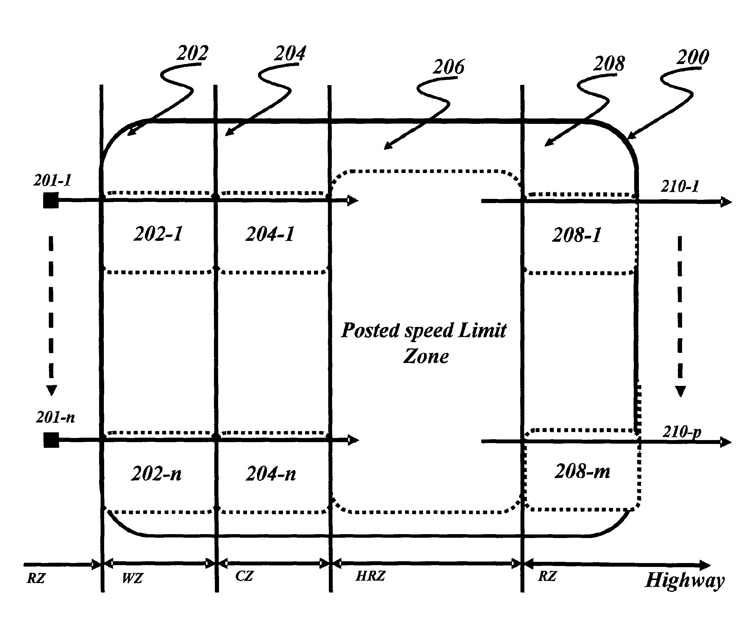
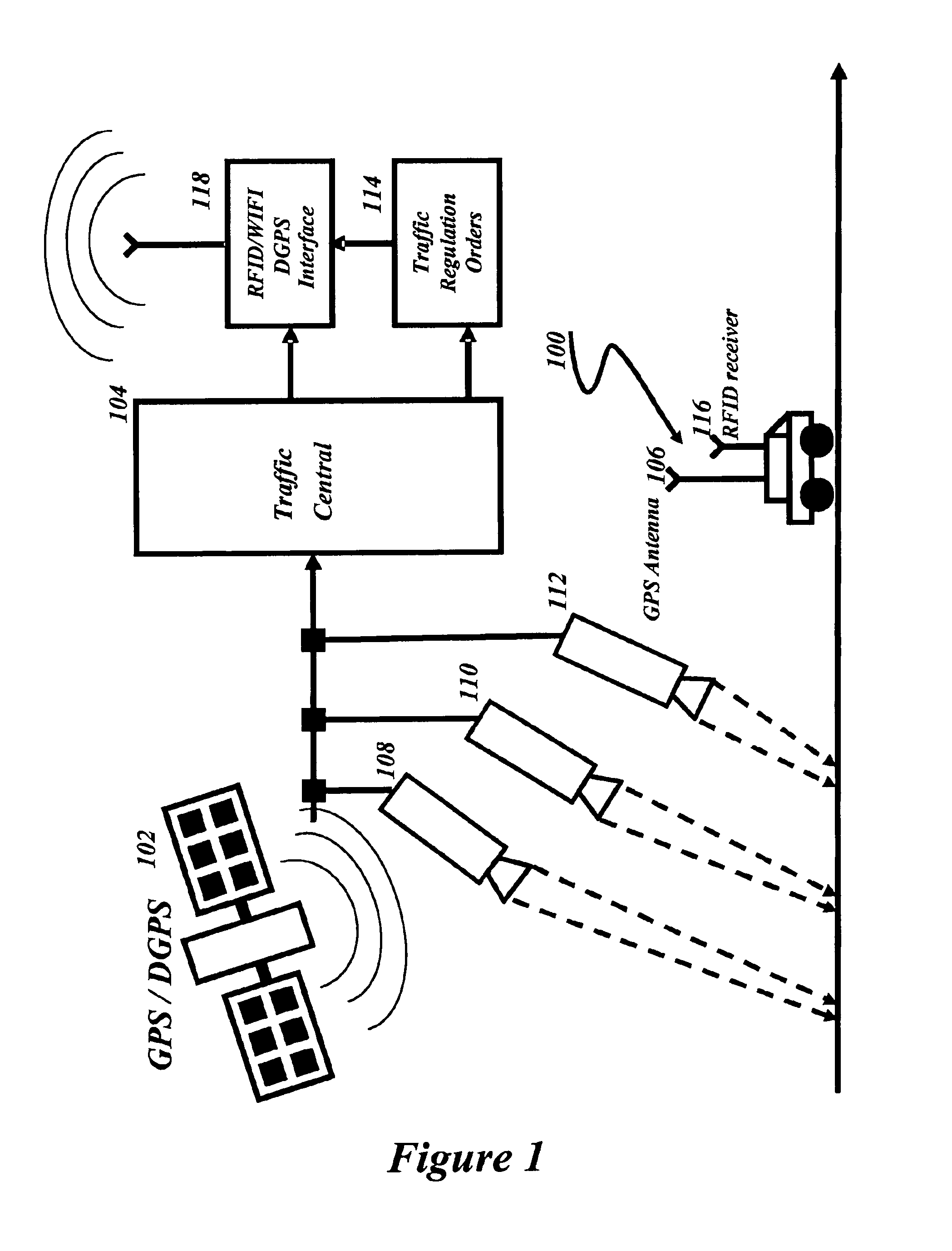
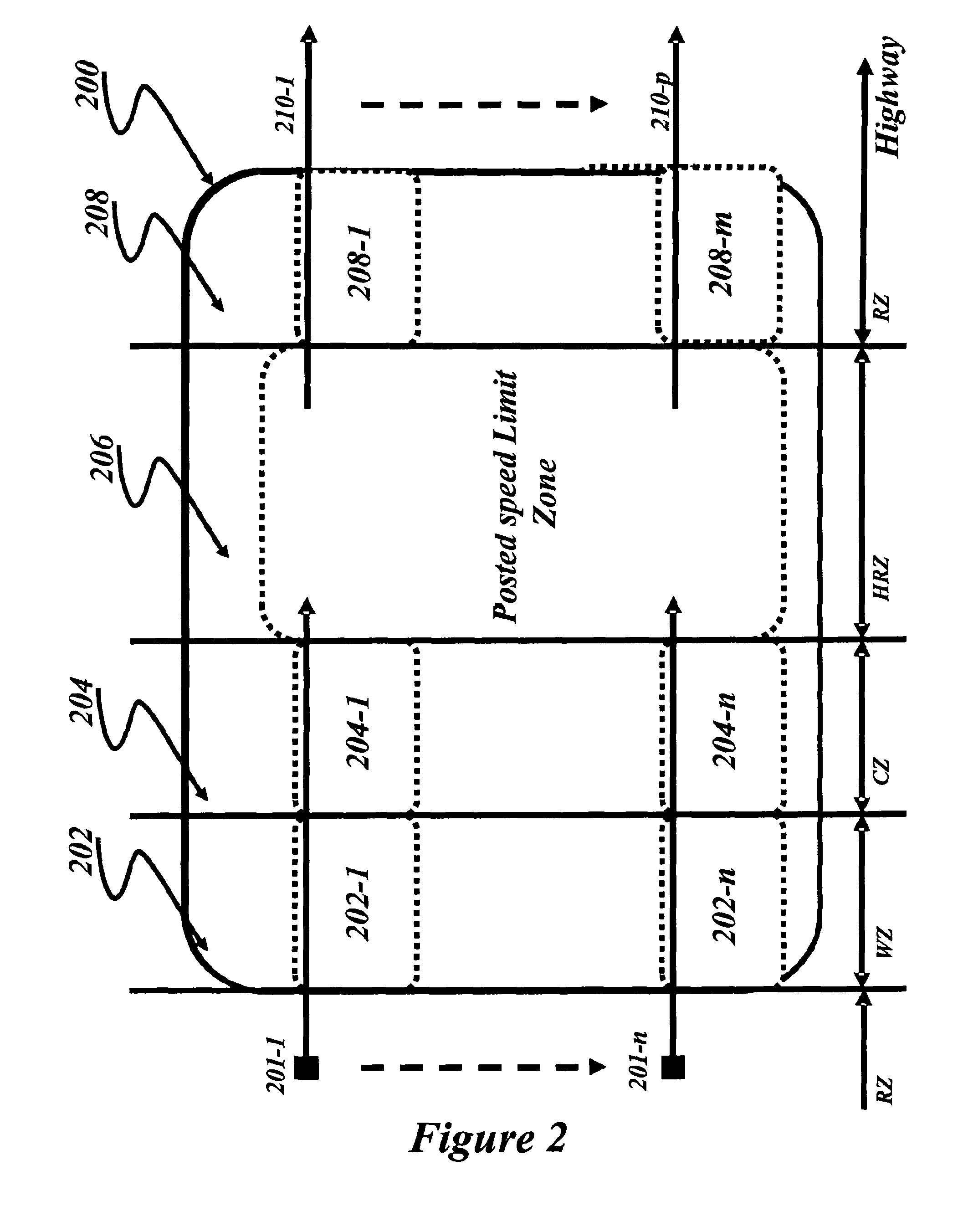
[0031]Refer now to the drawings wherein depicted elements are not necessarily shown to scale and wherein like or similar elements are designated by ...


PUM


Abstract

A method and system for monitoring speed of a vehicle moving along a road that includes risk zones. The method determines: road conditions for each risk zone; a threshold speed of each risk zone based on the road conditions and on a distance to a posted speed limit within a high risk zone; a geographical position of the vehicle, a current risk zone in which the vehicle is moving based on the stored geographical position of the vehicle; and a current speed of the vehicle moving in the current risk zone which exceeds the threshold speed of a particular risk zone, resulting in performing a subsequent action (triggering an alarm within the vehicle, presenting a message to a driver in the vehicle, and / or automatically regulating the speed of the vehicle). The action is specific to the particular risk zone and dependent on the road conditions.

Description

TECHNICAL FIELD OF THE INVENTION[0001]The present invention relates generally to the field of vehicle speed regulation systems and, more particularly, to a method, system and program for auditing a vehicle speed compliance to an upcoming speed limit.BACKGROUND ART[0002]Speed limits and driving conditions along any given route may change frequently, particularly in urban settings. In addition, along a given route speed limits may change according to the time of day, such as during school hours or rush hours. The current and accepted method of informing the driver of the speed limit is through posted speed limit signs on the side of the road. However, it is easy for drivers to become distracted and not notice changes in speed limit sign postings. In addition, drivers may intentionally or unintentionally exceed the posted speed limit. Exceeding a posted speed limit can have negative consequences such as personal injury, property damage, and fines from speeding tickets. Moreover, when m...

Claims


Application Information

Patent Timeline
Patent Type & Authority Patents(United States)
IPC IPC(8): G01C21/32
CPCG08G1/052
Inventor BOULET, BERTRANDBREDIN, FRANCIS
Owner KYNDRYL INC
Learn More