Trans-rectum universal ports

a universal port and transrectum technology, applied in the field of surgical tools, can solve the problem that instruments cannot perform other actions or procedures, and achieve the effect of preventing the need for surgery

Active Publication Date: 2014-01-21
CILAG GMBH INT
View PDF1091 Cites 1232 Cited by
  • Summary
  • Abstract
  • Description
  • Claims
  • Application Information

AI Technical Summary

Benefits of technology

[0012]In connection with yet another general aspect of one form of the present invention, there is provided a modular surgical instrument system that comprises a handle assembly that has a manually-actuatable actuator trigger operably supported thereon for generating an actuation motion. An actuation system is operably supported by the handle assembly and is configured to generate a plurality of discrete drive motions in response to an application of the actuation motion thereto. The instrument further comprises an elongated shaft assembly that includes an outer shaft casing that has a distal end. A rotary drive shaft is operably supported within the outer shaft casing and is oriented for selective operable interaction with the actuation system. The instrument further comprises a first surgical tool head that is configured for interchangeable attachment to the distal end of the outer shaft casing such that upon attachment thereto, the first surgical tool head moves the rotary drive shaft to a first drive position wherein upon application of the actuation motion to the actuation system, the rotary drive shaft imparts a first rotary drive motion to the first surgical tool head to cause the first surgical tool head to perform a first surgical action. A second surgical tool head is configured for interchangeable attachment to the distal end of the outer shaft casing such that upon attachment thereto, the second surgical tool head moves the rotary drive shaft to a second drive position wherein upon application of the actuation motion to the actuation system, the rotary drive shaft imparts a second rotary drive motion to the second surgical tool head to cause the second surgical tool head to perform a second surgical action that differs from the first surgical action. A third surgical tool head is configured for interchangeable attachment to the distal end of the outer shaft casing such that upon attachment thereto, the third surgical tool head moves the rotary drive shaft to a third drive position wherein upon said application of said actuation motion to said actuation system, the rotary drive shaft imparts a third rotary drive motion to the third surgical tool head to cause the third surgical tool head to perform a third surgical action.

Problems solved by technology

However, such instruments cannot perform other actions or procedures that may also be required to complete a particular operation.

Method used


Image

  • Trans-rectum universal ports
  • Trans-rectum universal ports
  • Trans-rectum universal ports

Examples


embodiment 600

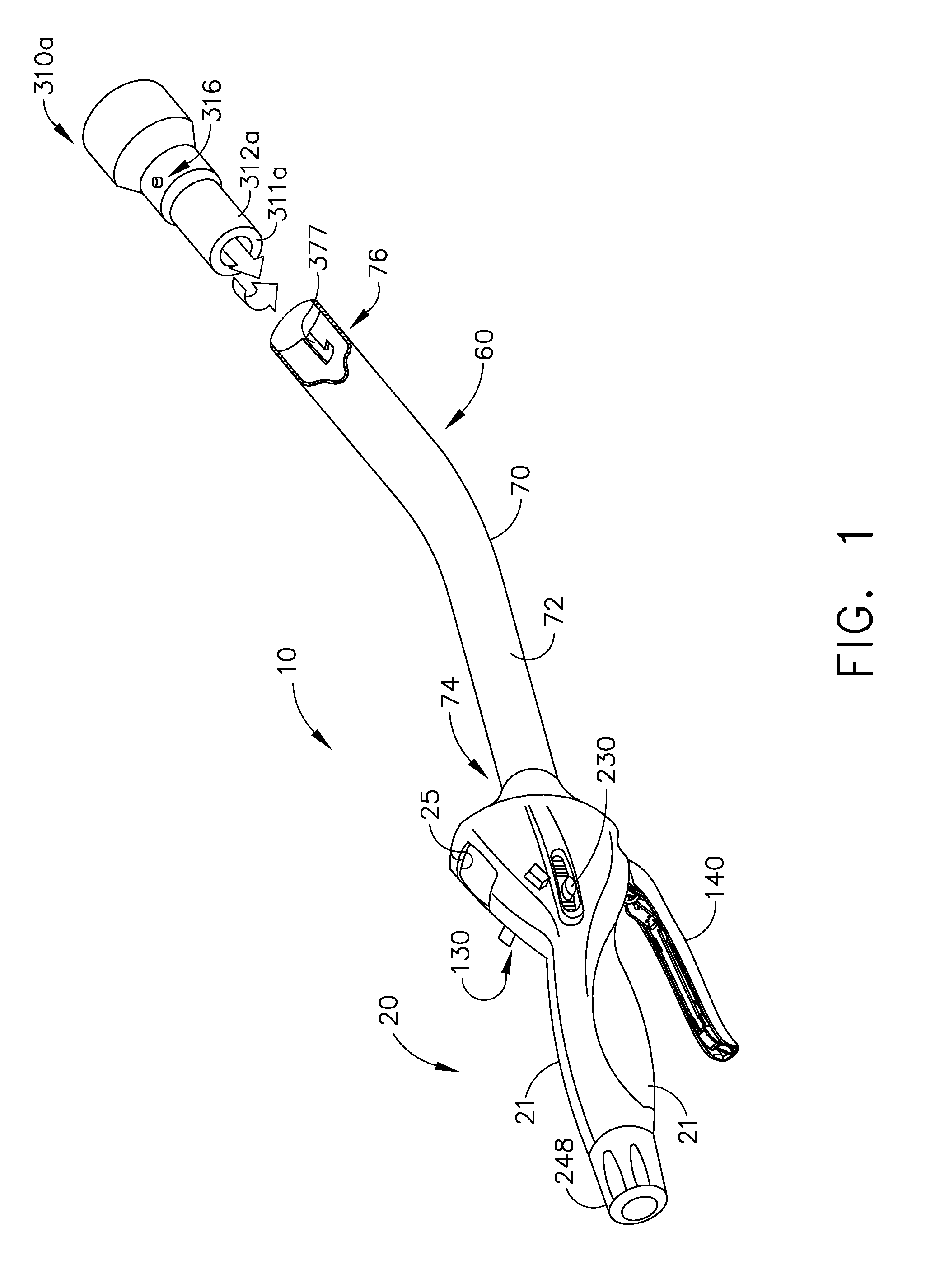
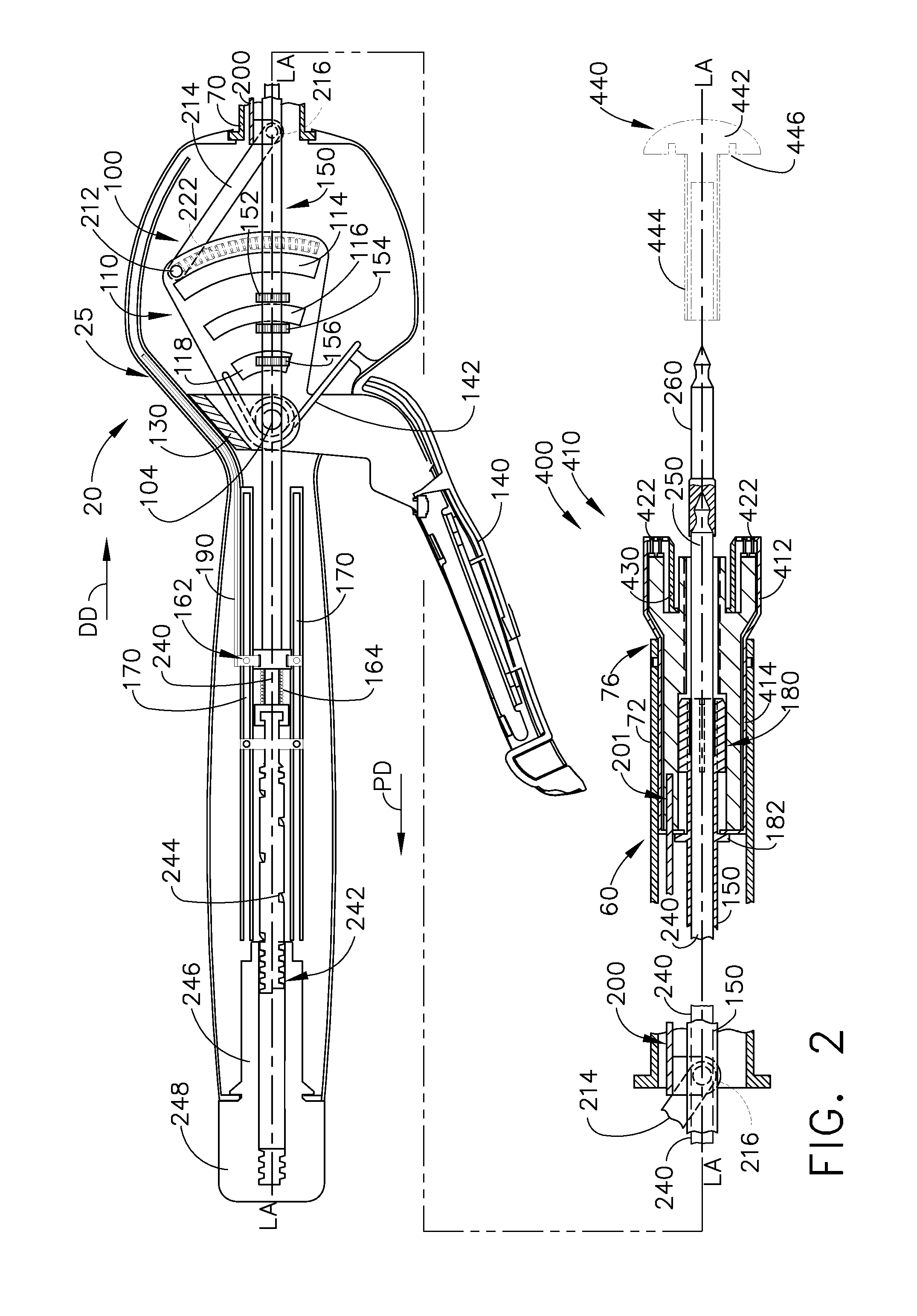
[0142]FIGS. 16 and 17 illustrate another surgical tool head embodiment 600 that may be effectively used in connection with various embodiments of the modular surgical instruments 10 of the present invention. In this embodiment, the surgical tool head 600 comprises a grasper head 610. This embodiment requires the application of a rotary drive motion to actuate the two movable jaws 670, 680 thereof. As can be seen in those Figures, the grasper head 610 has an outer casing 612 that has an attachment stem portion 614 that is sized to be seated into the distal end 76 of the outer shaft casing 70. Attachment pins 616 protrude from the attachment stem 614 and are configured to be received within the bayonet slots 377 in the outer shaft casing 70. The first and second movable jaws 670, 680 are pivotally pinned to the distal end 616 of the casing 612 for pivotal travel about a common pivot axis between an open position (FIG. 16) and a closed position (FIG. 17). The first movable jaw 670 has ...

embodiment 700

[0145]FIGS. 18-20 illustrate another surgical tool head embodiment 700 that may be effectively used in connection with the various embodiments of the modular surgical instruments 10 of the present invention. In this embodiment, the surgical tool head 700 comprises a grasper head 710. This embodiment requires the application of a rotary drive motion to actuate the two movable jaws 770, 780 thereof. As can be seen in those Figures, the grasper head 710 has an outer casing 712 that has an attachment stem portion 714 that is sized to be seated into the distal end 76 of the outer shaft casing 70. Attachment pins 716 protrude from the attachment stem 614 and are configured to be received within the bayonet slots 377 in the outer shaft casing 70. The first and second movable jaws 770, 780 are pivotally pinned to the distal end 716 of the casing 712 for pivotal travel about a common pivot axis between an open position (FIG. 18) and a closed position (FIG. 19). The first movable jaw 770 has ...

embodiment 800

[0147]FIG. 21 illustrates another surgical tool head embodiment 800 that may be effectively used in connection with the various embodiments of the modular surgical instruments 10 of the present invention. In this embodiment, the surgical tool head 800 comprises a circular stapler head 810 that has an outer casing 812 that supports a circular staple cartridge 820 therein. The anvil has been omitted from the Figure for clarity. However, the reader will understand that, except for the differences noted below, the circular stapler head 810 may otherwise operate in the same manner as the stapling heads described above. The circular staple cartridge 820 movably supports an outer circular array 822 of staple drivers 824 and an inner circular array 826 of staple drivers 827. Each staple driver 824, 827 supports one or more surgical staples 828 thereon. This embodiment requires the application of a rotary drive motion to a rotary drive assembly 830 that is rotatably supported within the circ...


PUM


Abstract

Various universal ports for installation into a colon are disclosed. Various embodiments include expandable port bodies that may employ selectively deployable tissue-engaging barbs for securing the port in position within the colon. Some embodiments also employ tissue cutting members that may be deployed to sever the colon. Some embodiments also employ a flexible sleeve that may extend from the port out through the anus to provide a passageway for passing surgical instruments and into and out of the rectum and also for removing severed specimens therefrom.

Description

CROSS-REFERENCE TO RELATED APPLICATIONS[0001]This non-provisional patent application claims the benefit of and priority from U.S. Provisional Patent Application Ser. No. 61 / 452,432, filed Mar. 14, 2011, entitled “Surgical Stapling Instruments”, the entire disclosure of which is hereby incorporated by reference.FIELD OF THE INVENTION[0002]The present invention generally relates to surgical devices for performing a variety of surgical procedures, and more particularly, to a surgical tool system that comprises a single handle assembly that can be employed with different tool attachments that are capable of performing different surgical procedures and actions.BACKGROUND[0003]Circular instruments are used to perform a number of surgical procedures. Such procedures often require the use of several different circular instruments that have a desired diametric size, shaft length and shaft geometry. Hospitals require storage space to inventory multiple product codes to satisfy these procedure...

Claims


Application Information

Patent Timeline
Patent Type & Authority Patents(United States)
IPC IPC(8): A61B1/32
CPCA61B2017/00287A61B2017/07257A61B17/1155A61B17/3417A61B17/00234A61B2017/00477A61B17/072F04C2270/0421A61B17/068A61B17/07207A61B17/0218A61B17/0293A61B2017/0225A61B2017/0287A61B2017/00353A61B2560/0443
Inventor YOO, ANDREWCHEKAN, EDWARD G.SHELTON, IV, FREDERICK E.HALL, STEVEN G.
Owner CILAG GMBH INT
Why Eureka
Try Eureka