
Self-aligning handling or storing device

a self-aligning and storage device technology, applied in the direction of handcuffs, flexible container closures, snap fasteners, etc., can solve the problems of unsightly approach, difficult to resolve, and unsafe,

Active Publication Date: 2014-01-28
GINOCCHIO MARK H
View PDF66 Cites 20 Cited by
  • Summary
  • Abstract
  • Description
  • Claims
  • Application Information

AI Technical Summary

Benefits of technology

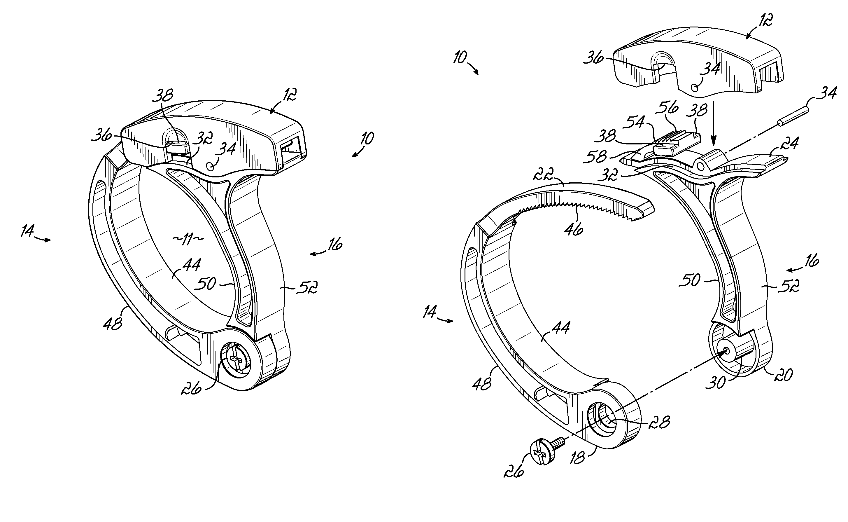
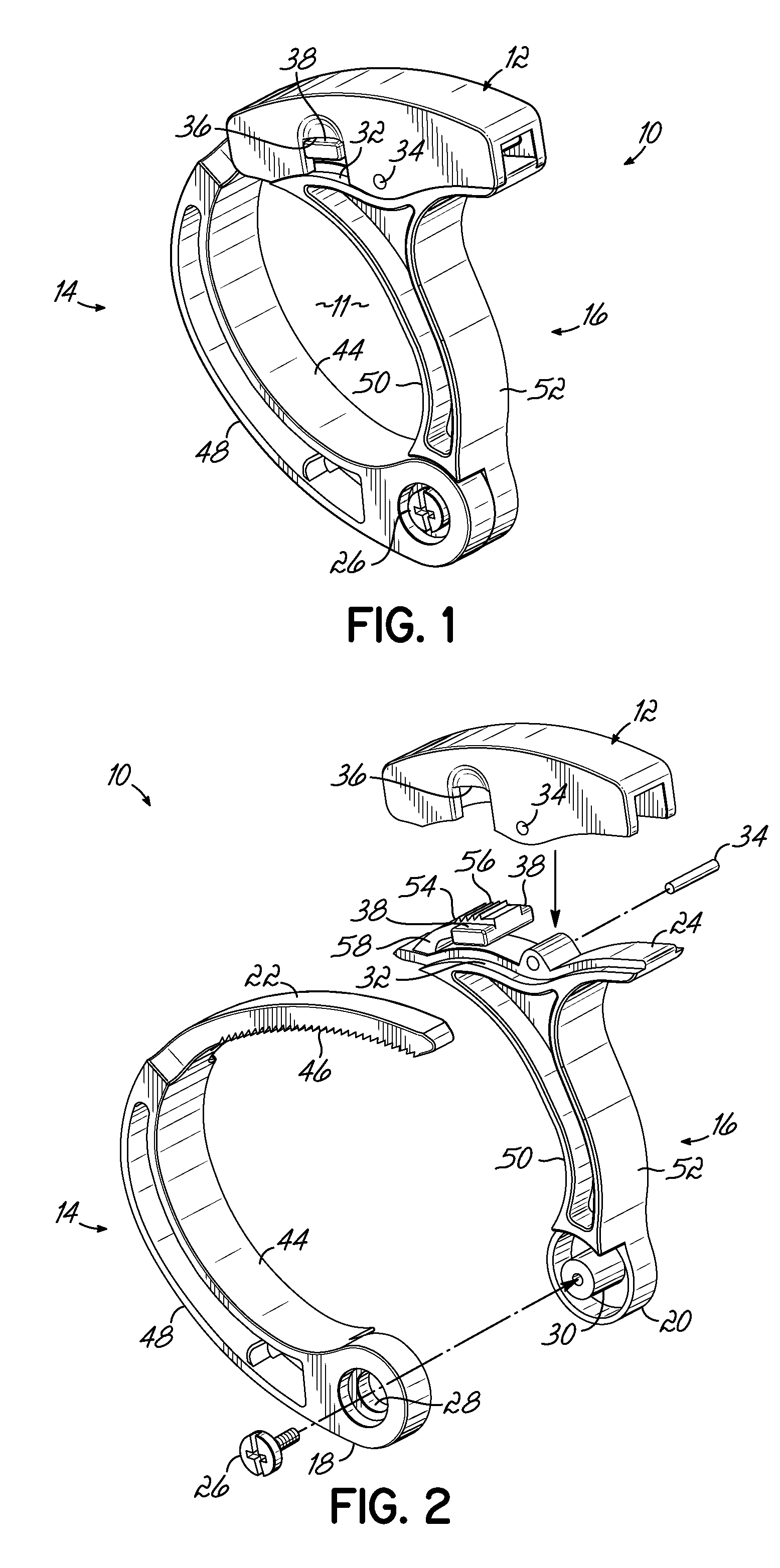
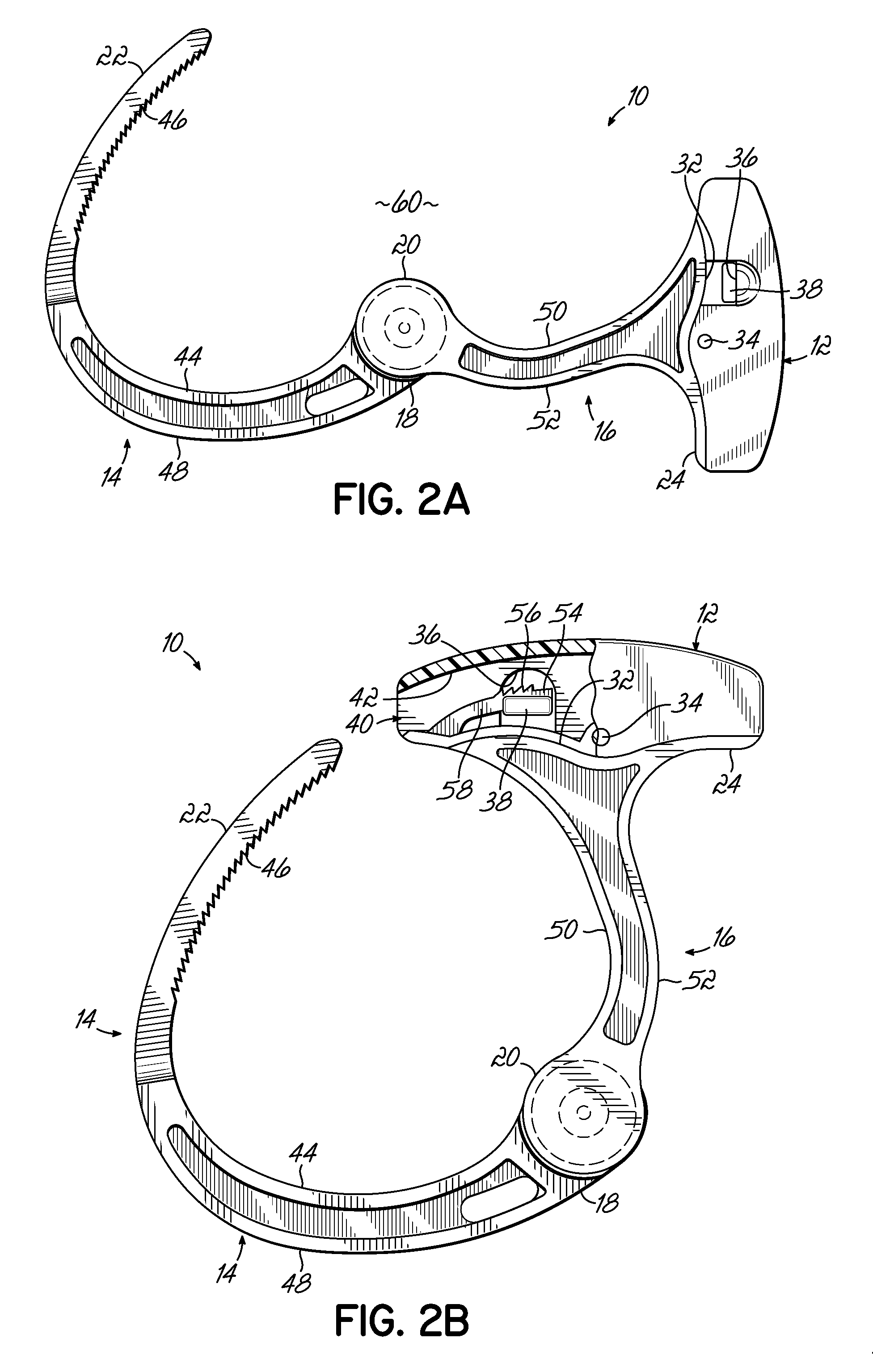
The invention features a device for handling or storing items that has two jaw members that can be opened and closed. The jaw members are connected together at their hinge ends, making them self-aligning. An engagement device is attached to the outer end of one jaw member and is made of a flexible material that can be moved between an engaged and disengaged position. The first and second jaw members are made of different materials, and the engagement device has a pawl portion, a beam portion, and an anchor portion. The invention allows for secure and easy handling of items.

Problems solved by technology

Handling and / or storage of items has presented numerous challenges, and despite the various handling and storage devices that have been devised, several problems continue to be difficult to resolve.
One example is the problem of storage of electrical cords or cables.
Such an approach is unsightly and can be unsafe.
Indeed, without better organization of the cords, storage can become a nightmare.
However, such items are very difficult to use and require a great deal of manual dexterity.
In particular, closing these ties around the bundled cord is quite challenging because the ends are free to go wherever they are pushed.
Some of those items, and particularly twist-ties such as are used to close garbage bags, are unsightly, have only a short useful life, and can present a risk of injury due to the metal wire contained therein.
Other cable management devices have been proposed, but they are usually quite bulky and again require a great deal of manipulation.
Such a device is difficult to load with the bundled wire because the ends are normally urged together into a closed or nearly-closed position.
When not attached to a cable or wire, a small wire tie or similar device is easy to lose.
Also, such devices are typically designed for limited use, e.g., they cannot be non-destructively removed, or will experience substantial wear (e.g., metal fatigue) if repeatedly opened and closed.
Thus, one cannot avoid losing a twist tie or wire tie by attaching it to the unbundled cable, since doing so will require destruction or damage to the twist tie or wire tie.
This is a particular drawback in storage of cables which must be repeatedly bundled and unbundled, e.g., extension cords used with hand tools, portable computer cabling, and other similar applications.
Aside from bundles of wires, in various other situations, objects must be wrapped and held for storage, handling or other reasons; often wire ties, twist ties, or lengths of string are used in such situation, with unsatisfactory results for the same reasons as those noted above: difficulty in use, likelihood of loss, and destruction and wear resulting from repeated use.
This pulling action can be difficult and inconvenient depending upon the orientation, size, and location of the bundle.
Devices such as those of U.S. Pat. Nos. 5,729,872 and 6,101,684 could benefit the user of earbuds if they could be made in very small sizes, but their unlatching actions tend to limit how small they can go and still be easily used by the human hand.

Method used


Image

  • Self-aligning handling or storing device
  • Self-aligning handling or storing device
  • Self-aligning handling or storing device

Examples


embodiment 850

[0093]FIG. 19 illustrates an embodiment 850. Device 850 has a mount 852 hinged from a cap 854. The mount has an aperture 856 that may be used for any of the hook 830, straight peg 832, or peg 833. A jaw member 858 includes an open handle 860.

[0094]As seen in FIGS. 20A and 20B, a handle 862 may be made detachable, for example by having a T-slot 864 in the jaw member 16. By making the handle detachable, a common manufacturing process may be used to make the planar jaw members with a common T-slot, and a wide variety of arms may be provided to install in the T-slot depending on customer preference.

[0095]FIG. 21 illustrates a device 870 having a first jaw member 874 with teeth 885 and a second jaw member 876 with an aperture 877 and trigger frame 878. In the trigger frame is a tongue groove 880 a pair of forward holes 881 and rear holes 882. A trigger assembly 884 has a pawl portion 886 and an anchor portion 888. Fasteners in the form of pins 889 pass through the holes 881 and 882 and h...

embodiment 910

[0103]FIGS. 24A-25B illustrate an embodiment 910 of a hand cuff like element adapted to be mounted to a flat surface. Device 910 may be conveniently used to organize cords routed across a flat surface, for example a desk or a ceiling. Device 910 has a jaw member 914 and a jaw member 916 with a generally flat face 918. Jaw 914 enters a passage 919 to engage tooth 920. A button 922 in hole 923, when pushed, releases jaw 914 so that it can be removed from the passage 919.

[0104]With reference to FIGS. 25A and 25B, the jaw 916 has a cavity 924 that receives a spring 926, a pawl 928 having the tooth 920, and a base 930 that is secured within the cavity by fasteners 932. The pawl 928 has a spring bore 934 that captures spring 926, and slidably locates in a spring guide 936 in the base. The pawl also has a guide 938 captured by a channel 940 of the base. At least one of hole 923, guide 936 and guide 938 receive a load force (not shown) transmitted when jaw member 914 is pulled in the direct...


PUM


Abstract

A device for handling or storing one or more items, has a pair of generally rigid jaw members each having a hinge end and an outer end. The jaw members have a first, open position in which the outer ends are spaced apart to define a receiving space and a plurality of closed positions. The jaw members are self aligned and one of them has an engagement member to engage the other. The engagement member is separate from either jaw member, and may therefore be made of a different material.

Description

RELATED APPLICATION[0001]This application is related to application U.S. Ser. No. 12 / 038,514 filed Feb. 27, 2008 and U.S. Pat. Nos. 5,729,872 and 6,101,684, each naming the same inventor as the present application, all three of which are hereby incorporated by reference in their entireties. This application is related to application Ser. Nos. 12 / 794,474 and 12 / 794,417 concurrently herewith.FIELD OF THE INVENTION[0002]The present invention relates to devices for capturing items, such as for handling or storage of electrical cords or cables or other applications.BACKGROUND OF THE INVENTION[0003]Handling and / or storage of items has presented numerous challenges, and despite the various handling and storage devices that have been devised, several problems continue to be difficult to resolve.[0004]One example is the problem of storage of electrical cords or cables. Many people tend to leave their cords simply in a pile. Such an approach is unsightly and can be unsafe. Indeed, without bet...

Claims


Application Information

Patent Timeline
Patent Type & Authority Patents(United States)
IPC IPC(8): F16B2/02
CPCH02G3/32H02G3/00Y10T70/404Y10T24/1422Y10T24/15Y10T24/44248Y10T24/4453F16B2/02B65D63/00
Inventor GINOCCHIO, MARK, H.
Owner GINOCCHIO MARK H
Learn More