Light emitting device
a technology of light-emitting devices and mounting brackets, which is applied in the direction of semiconductor devices, basic electric elements, electrical apparatus, etc., can solve the problems of unstable mounting, adversely affecting productivity, and adding complexity, and achieves the effect of high mounting stability and any productivity drop
- Summary
- Abstract
- Description
- Claims
- Application Information
AI Technical Summary
Benefits of technology
Problems solved by technology
Method used
Image
Examples
embodiment 1
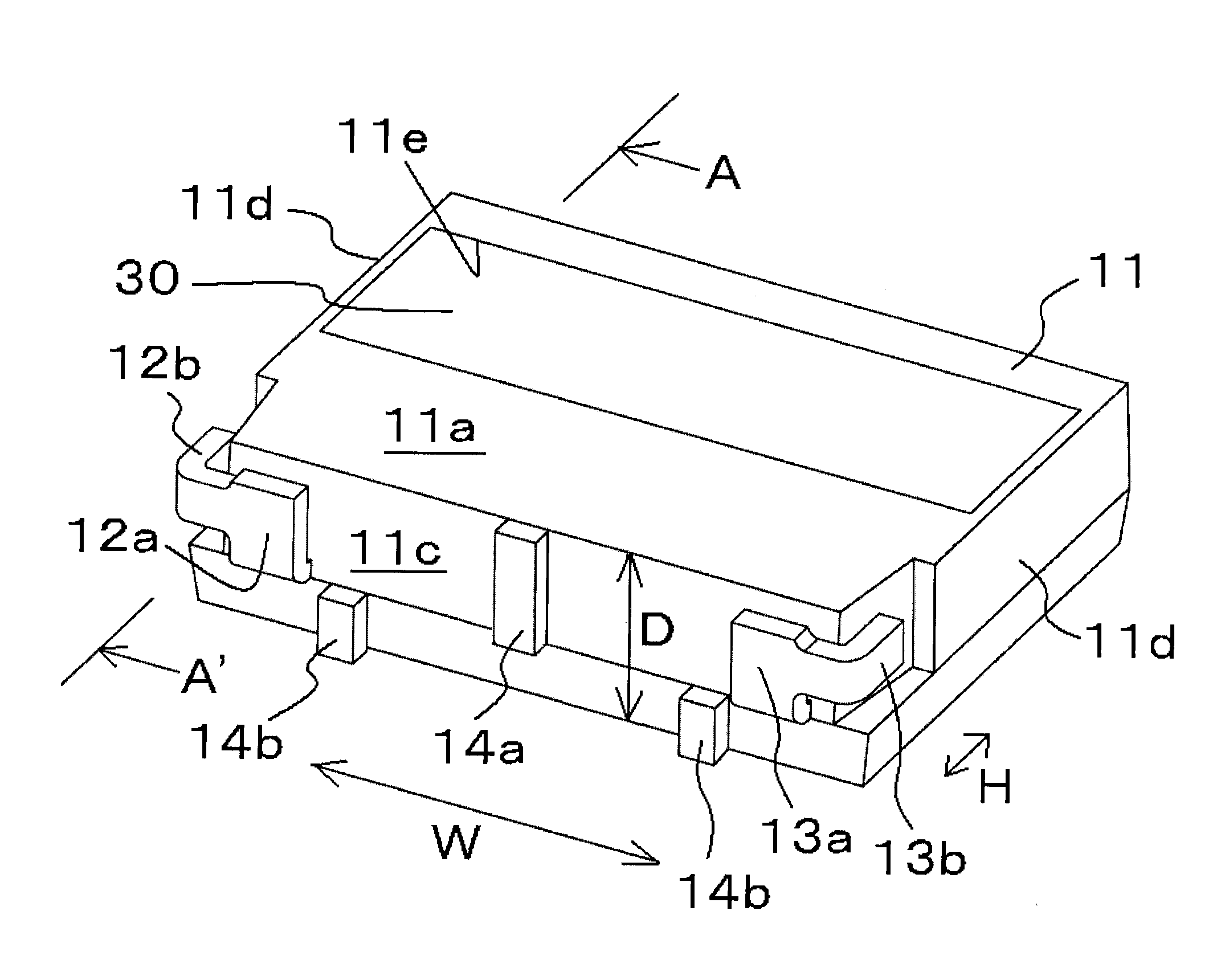
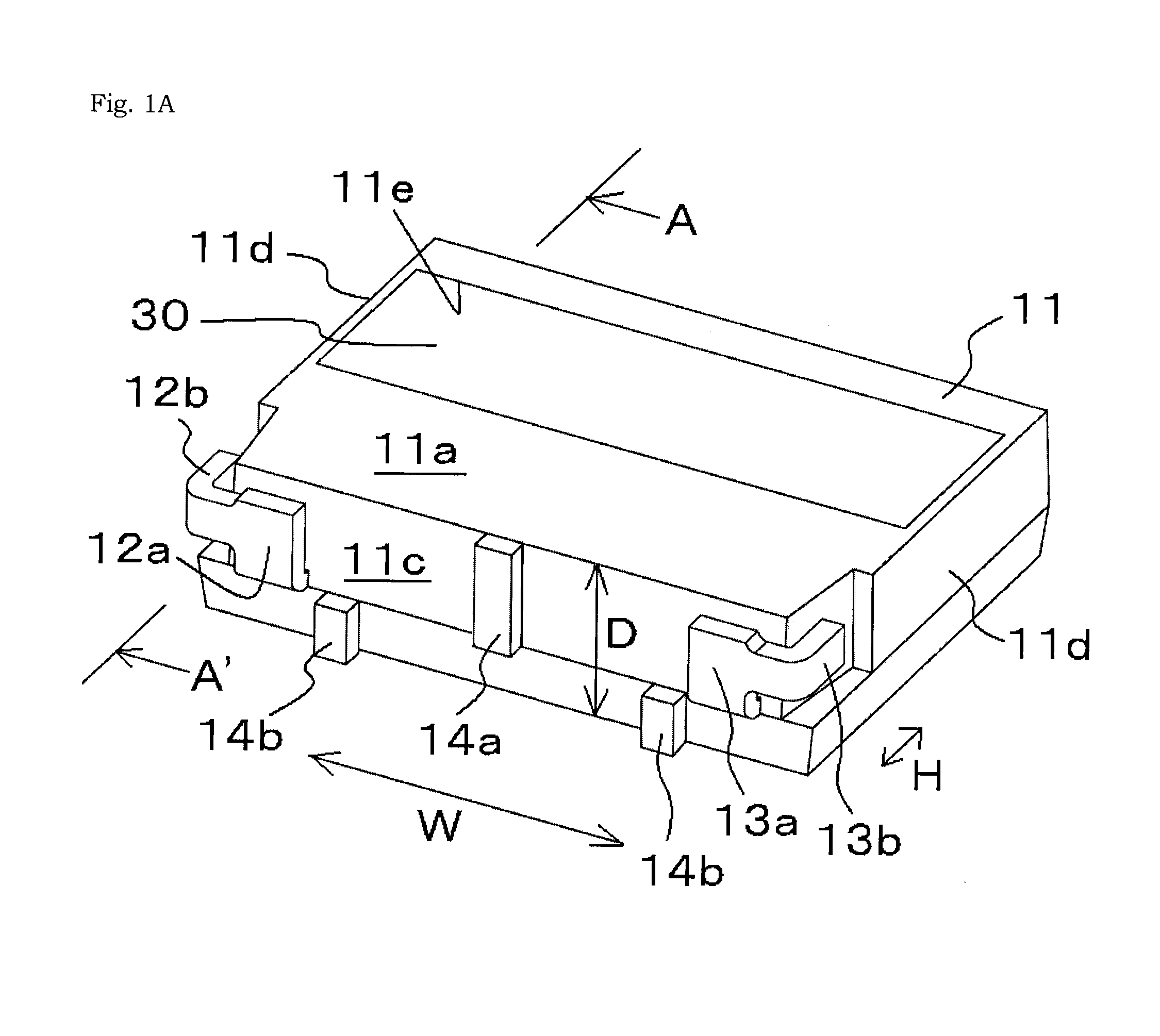
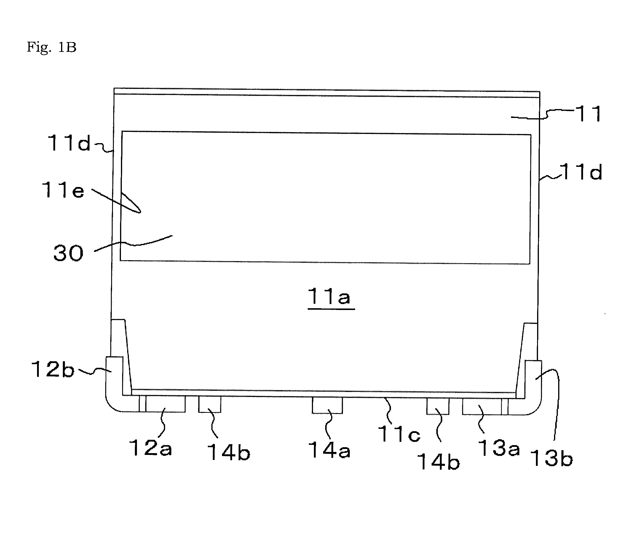
[0034]As shown in FIGS. 1A to 1E, the light emitting device in this embodiment mainly comprises a package and a light emitting element 20.
[0035]This light emitting device is what is called a side view type. A side-view light emitting device is a type in which the light emitted from the light emitting element is taken out in a direction parallel to a mounting face of a mounting board. These side-view light emitting devices are generally small in the depth direction, and one of their characteristics is they are more prone to toppling forward or backward than what is known as a top-view light emitting device.
[0036]The package has a molded article 11 composed of a resin, and a pair of leads 12 and 13 that are partially embedded in the molded article 11.
Molded Article 11
[0037]The molded article 11 is usually formed in a substantially cuboid shape, and defines the external shape of the package. The shape of the molded article 11 is not limited to being cuboid, however, and may inst...
embodiment 2
[0061]As shown in FIGS. 2A to 2C, the light emitting device in this embodiment is the same as the light emitting device in Embodiment 1 in that it comprises a light emitting element (not shown) and a package having a molded article 21 composed of resin and a pair of leads 12 and 13 that are partially embedded in this molded article 21.
[0062]The leads 12 and 13 protrude from the bottom face 21b of the molded article 21, and the protruding leads 12 and 13 have ends 12a and 13a that are bent to a light emitting face 21a side along the bottom face of the molded article 21. Also, ends 12a and 13a have distal ends 12b and 13b that are bent along side faces 21d of the molded article 21.
[0063]The molded article 21 comprises one each of a front protruding part 24a that protrudes on the light emitting face 21a side and a rear protruding part 24b that protrudes on the rear face 21b side, between the leads 12 and 13 on the bottom face 21c, and near each of the leads 12 and 13.
[0064]The light em...
embodiment 3
[0065]As shown in FIGS. 3A to 3C, the light emitting device in this embodiment is that same as the light emitting device in Embodiment 1 in that it comprises a light emitting element (not shown) and a package having a molded article 31 composed of resin and a pair of leads 32 and 33 that are partially embedded in this molded article 31.
[0066]The leads 32 and 33 protrude from the bottom face 31b of the molded article 31, and the protruding leads 32 and 33 have ends 32a and 33a that are bent to a light emitting face 31a side along the bottom face of the molded article 31. Also, ends 32a and 33a have distal ends 32b and 33b that are bent along side faces 31d of the molded article 31.
[0067]The lead 32 has an installation face for installing a light emitting element disposed inside the molded article 31, extends in one direction from this installation face, protrudes from the bottom face 31b of the molded article 31 to form the end 32a and the distal end 32b, and also extends in another ...
PUM
 Abstract
Description
Claims
Application Information
 - R&D
- Intellectual Property
- Life Sciences
- Materials
- Tech Scout
- Unparalleled Data Quality
- Higher Quality Content
- 60% Fewer Hallucinations
Browse by: Latest US Patents, China's latest patents, Technical Efficacy Thesaurus, Application Domain, Technology Topic, Popular Technical Reports.
© 2025 PatSnap. All rights reserved.Legal|Privacy policy|Modern Slavery Act Transparency Statement|Sitemap|About US| Contact US: help@patsnap.com


