Control system

a control system and remote control technology, applied in the direction of vehicle position/course/altitude control, process and machine control, instruments, etc., can solve the problems of lag time, error, inability to see movement, etc., and achieve the effect of zero measured vehicle speed and zero measured vehicle speed

Active Publication Date: 2014-02-11
GE GLOBAL SOURCING LLC
View PDF9 Cites 8 Cited by
  • Summary
  • Abstract
  • Description
  • Claims
  • Application Information

AI Technical Summary

Benefits of technology

[0011]In another embodiment, an inventive article includes non-transitory computer readable media encoded with one or more sets of instructions. When executed by a controller of a rail vehicle, the instructions cause the controller to respond to signals received from an off-board control unit. Responsive to a first signal received from an off-board control unit, the first signal indicative of a first mode of operation, the controller is configured to idle a traction power system of the rail vehicle and continuously apply all brakes of the rail vehicle to achieve and maintain zero measured vehicle speed. Responsive to a second signal received from the off-board control unit, the second signal indicative of a second mode of operation, the controller is configured to idle the traction power system and continuously apply selected brakes of the rail vehicle to achieve and maintain zero measured vehicle speed. Responsive to a third signal received from the off-board control unit, the third signal indicative of a third mode of operation, the controller is configured to adjust the traction power system to achieve measured vehicle speed matching an ordered vehicle speed. Responsive to a fourth signal received from the off-board control unit, the fourth signal indicative of a fourth mode of operation, the controller is configured to idle the traction power system and monitor measured vehicle speed.

Problems solved by technology

Due to the presence of multiple stationary rail cars or stub trains on intervening tracks, an operator in a locomotive moving on a first track may not be able to see moving cars on a track branching from the first track.
Three-way communication between operators and a yardmaster can introduce lag time and error, which are undesirable while moving multiple pieces of heavy rail equipment.

Method used


Image

  • Control system
  • Control system
  • Control system

Examples


Embodiment Construction

[0018]Reference will be made below in detail to exemplary embodiments of the invention, examples of which are illustrated in the accompanying drawings. Wherever possible, the same reference numerals used throughout the drawings refer to the same or like parts.

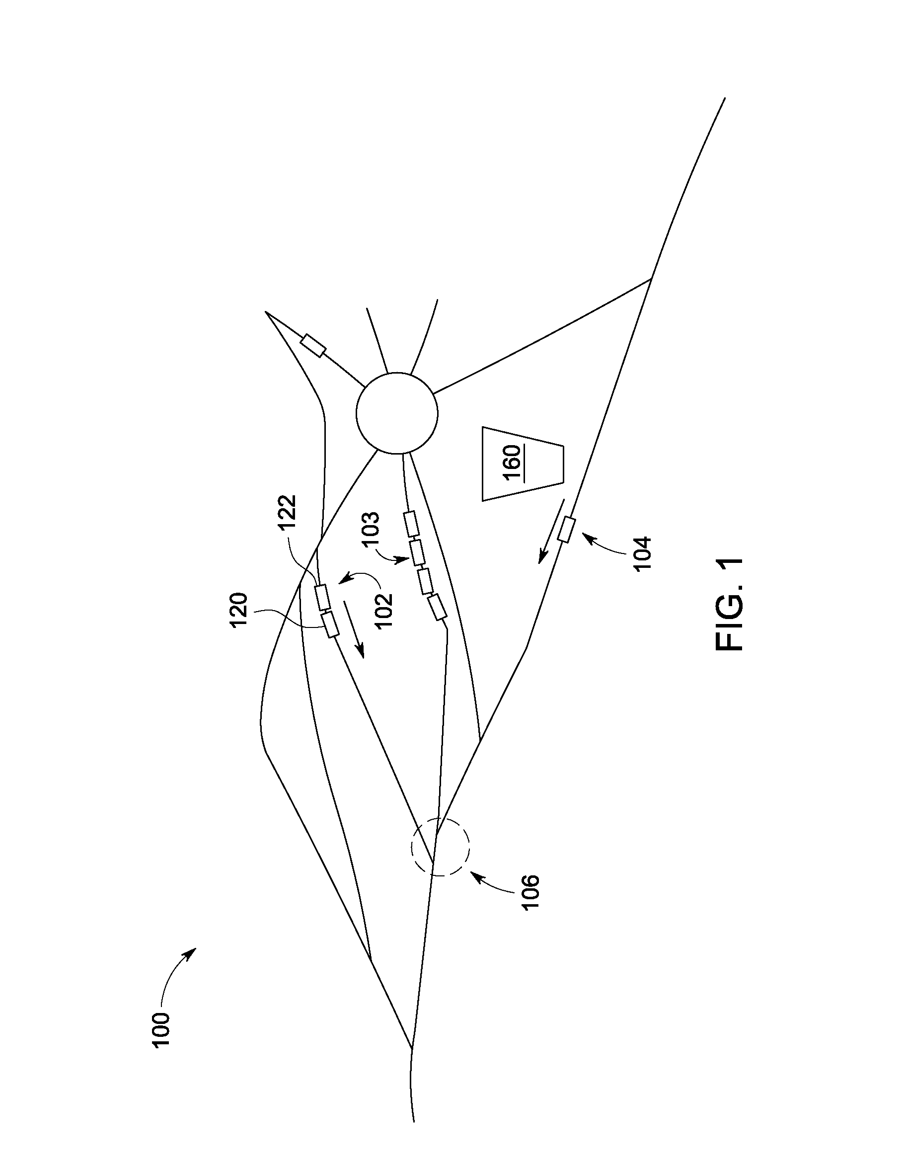
[0019]FIG. 1 shows in a schematic view a rail classification yard 100, in which three trains 102, 103, 104 are positioned. Train 102 and locomotive 104 both are moving along separate tracks toward a common junction 106, and will arrive at approximately the same time. Both trains 102 and 104 are stub trains. Train 102 consists of car 120 pushed by locomotive 122. Train 104 consists solely of a locomotive. Importantly, intermediate train 103 obscures visibility of train 102 from locomotive 104 and also obscure visibility of locomotive 104 from locomotive 122. Thus, if the two trains are individually operated, it is possible that they will in fact collide at the common junction 106. As discussed above, one solution to this problem...


PUM


Abstract

A control system for rail vehicles includes an operator control unit in communication with an on-board transceiver housed in a rail vehicle. The operator control unit includes a selector manually movable to a plurality of pre-determined positions each position corresponding to one of at least the following modes of operation: FORWARD, REVERSE, and COAST, such that for each pre-determined position of the selector, the operator control unit sets the off-board control unit to the corresponding mode of operation.

Description

FIELD OF THE INVENTION[0001]Embodiments of the invention relate generally to control systems, and, more particularly, to remote control of rail vehicle traction power systems.BACKGROUND OF THE INVENTION[0002]Rail car switching, shunting, and classification are integral aspects of rail freight operations. These procedures are performed in switching yards or classification yards, which include multiple rail tracks branching from one or more lead tracks and joining together at one or more exits. To maximize operational efficiency, several cars or trains of cars are typically moving simultaneously along different branches within a yard. Due to the presence of multiple stationary rail cars or stub trains on intervening tracks, an operator in a locomotive moving on a first track may not be able to see moving cars on a track branching from the first track. Accordingly, locomotive operators may coordinate their actions via a yardmaster stationed in a control tower overlooking the yard.[0003...

Claims


Application Information

Patent Timeline
Patent Type & Authority Patents(United States)
IPC IPC(8): B61L3/00
CPCB61L17/00B61L3/127B61C17/12B61L15/0027
Inventor WOO, DEREK KPAULINO, CARLOS SBRYANT, ROBERT F
Owner GE GLOBAL SOURCING LLC
Why Eureka
Try Eureka