Baseplate dampening pad

a dampening pad and base plate technology, applied in seismic energy generation, seismic instruments, seismic data acquisition, etc., can solve the problems of inherently limit the power that is delivered into the ground at high frequency, slow and dangerous seismic acquisition types, and less than desirable high frequency energy intensity or amplitude in data record data

Active Publication Date: 2014-03-04
CONOCOPHILLIPS CO
View PDF11 Cites 12 Cited by
  • Summary
  • Abstract
  • Description
  • Claims
  • Application Information

AI Technical Summary

Problems solved by technology

This type of seismic acquisition was slow and dangerous.
However, it has long been recognized that high frequency energy provides a level of detail in the seismic record that is highly desirable, but the intensity or amplitude of the high frequency energy in the data record has been less than desirable.
The dynamics of vibrator systems seems to inherently limit the power that is deliverable into the ground at high frequency.
While the Sallas approximation indicates that a fast stroke of shorter length provides equal force to the ground, the absence of the higher frequency data in the data traces or records from the field could mean that either the true force is not what is approximated by the Sallas equation or that consistent force across a broad frequency spectrum does not deliver consistent energy delivery across a broad frequency spectrum.

Method used


Image

  • Baseplate dampening pad
  • Baseplate dampening pad
  • Baseplate dampening pad

Examples


Embodiment Construction

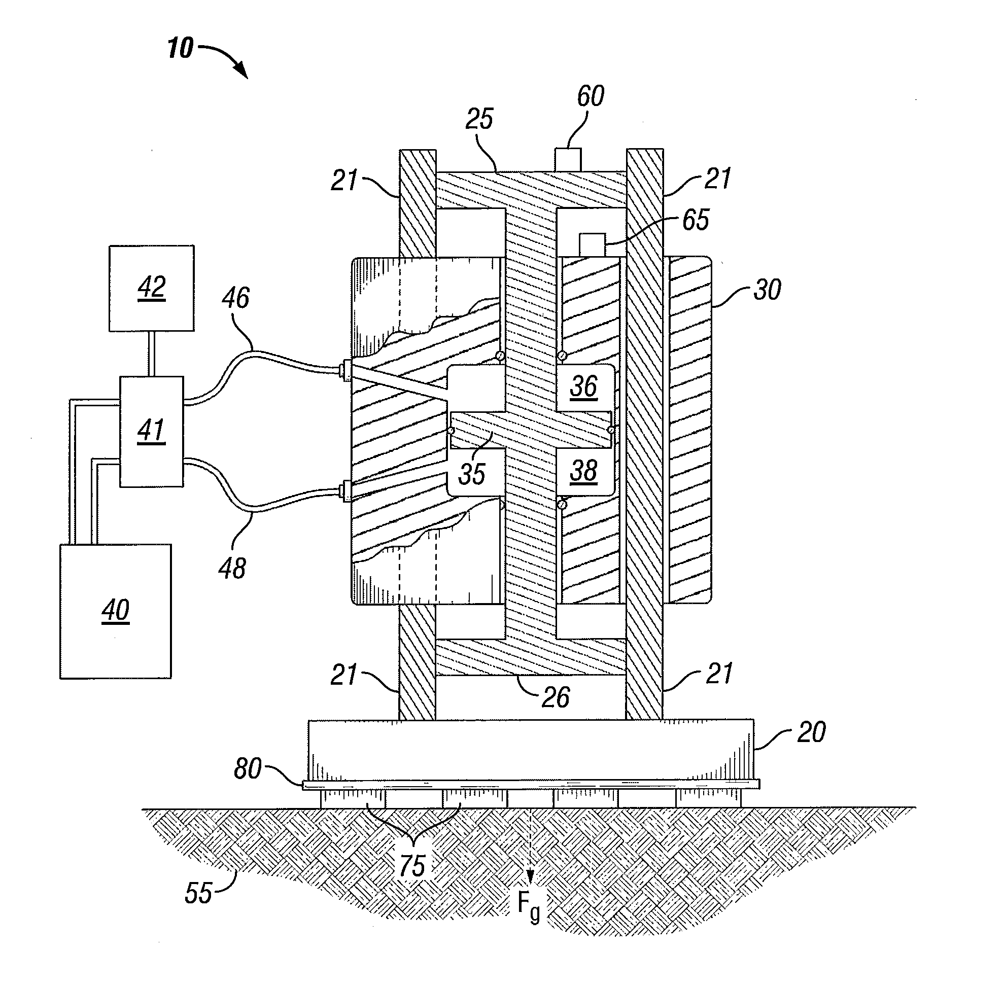
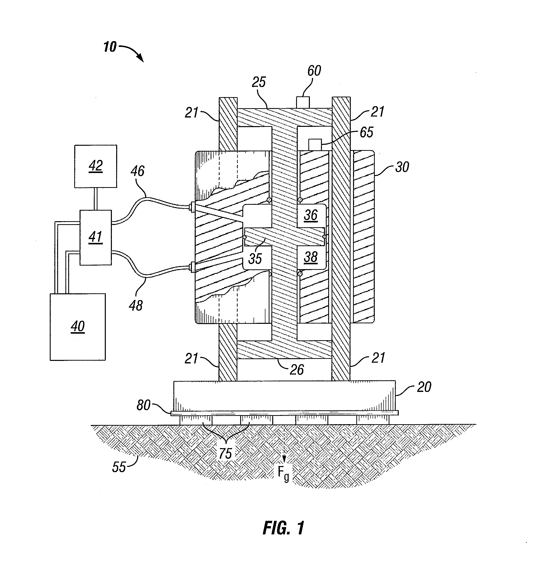
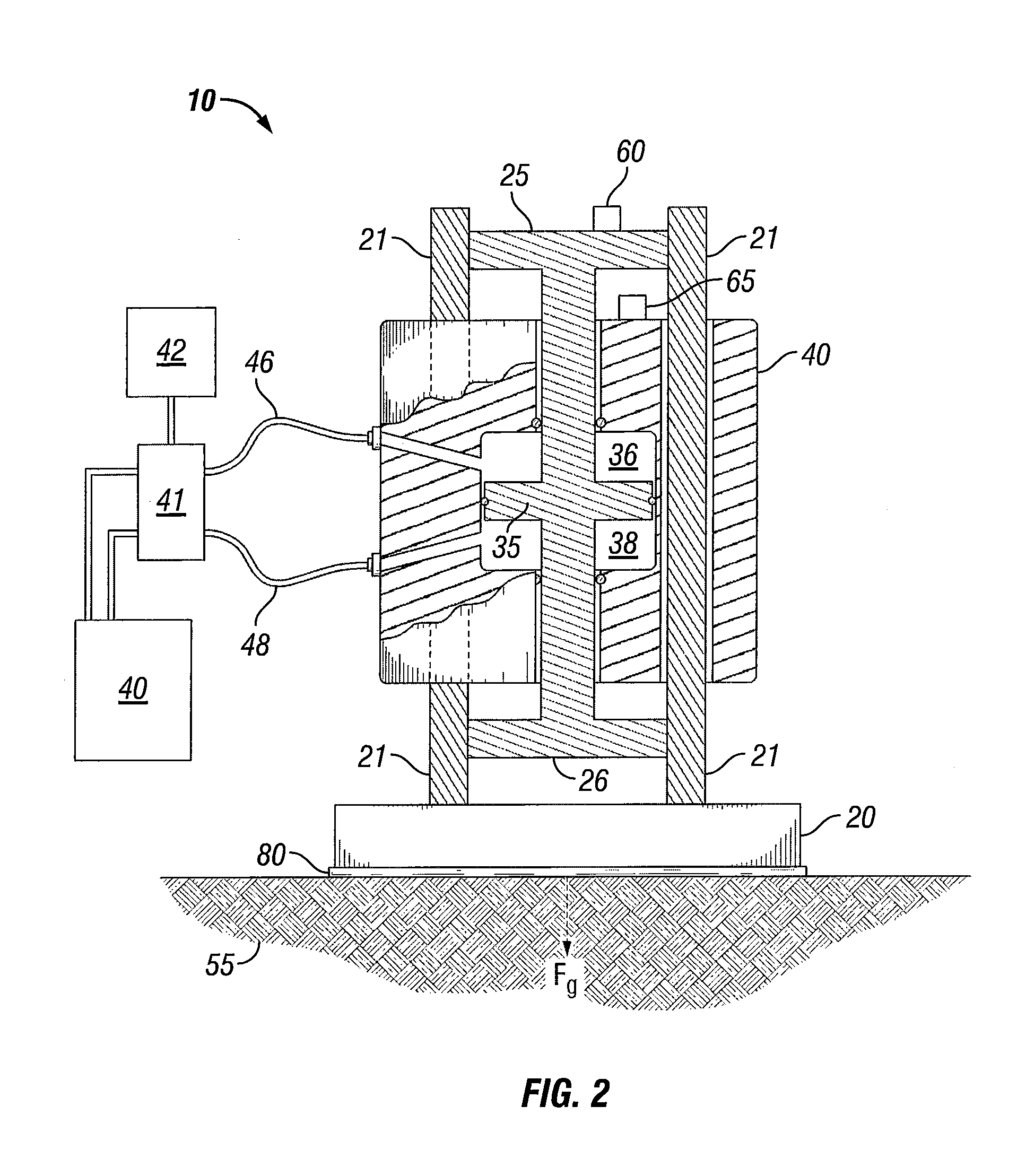
[0013]Turning now to the detailed description of the preferred arrangement or arrangements of the present invention, it should be understood that the inventive features and concepts may be manifested in other arrangements and that the scope of the invention is not limited to the embodiments described or illustrated. The scope of the invention is intended only to be limited by the scope of the claims that follow.

[0014]As noted above, it has been difficult to acquire suitable high frequency data when using sweep-type vibratory seismic sources and investigations pursuant to the present invention have turned toward an analysis of the energy that sweep-type vibratory seismic sources are actually putting into the ground in hopes of increasing the presence of high frequency data in the returning wavefield. The analysis begins with a seismic vibrator that one would plan to use in a seismic survey. For explaining the invention, a conventional sweep-type vibratory seismic source is illustrate...


PUM


Abstract

The invention relates to a sweep-type vibratory seismic source where a baseplate is put to the ground and a series of impulses are applied through the baseplate into the ground and where the baseplate may periodically de-couple from the ground during the delivery of the impulses. A de-coupling baseplate tends to undertake a very high frequency flexing while high frequency energy is being delivered to the ground. The high frequency flexing may be picked up by the vibrator control system and interpreted as an unintended signal being delivered into the ground. While there are already issues getting high frequency data in the return wave field, allowing the vibrator electronics to alter the actual signal in a manner intended to squelch the high pitched ringing of the baseplate is apt to reduce the high frequency data in the data record. One solution for reducing the de-coupling and the ringing of the baseplate is a dampening pad positioned between the baseplate and the ground.

Description

CROSS-REFERENCE TO RELATED APPLICATIONS[0001]This application is a non-provisional application which claims benefit under 35 USC §119(e) to U.S. Provisional Application Ser. No. 61 / 378,164 filed Aug. 30, 2010, “Baseplate Dampening Pad,” which is incorporated herein in its entirety.STATEMENT REGARDING FEDERALLY SPONSORED RESEARCH OR DEVELOPMENT[0002]None.FIELD OF THE INVENTION[0003]This invention relates to the acquisition of seismic data and especially to vibratory sources that provide seismic energy into the ground and create reflections from subsurface geology that is received and recorded in the form of seismic data.BACKGROUND OF THE INVENTION[0004]Historically, the acquisition of seismic data was accomplished by creating an explosion that propagated a broad frequency spectrum of seismic energy into the ground. The energy carried down into the ground reflecting and refracting off and through the various strata below the surface and the returning wavefield was recorded. This type ...

Claims


Application Information

Patent Timeline
Patent Type & Authority Patents(United States)
IPC IPC(8): G01V1/04
CPCG01V1/145
Inventor EICK, PETER M.BREWER, JOEL D.SHAN, SHAN
Owner CONOCOPHILLIPS CO
Why Eureka
Try Eureka