
Cooking tray and apparatus for securing cooking tray

a technology for cooking racks and cooking trays, which is applied in the direction of cooking inserts, kitchen equipment, show hangers, etc., can solve the problem that the products being cooked have a tendency to float away

Active Publication Date: 2014-03-18
WINSTON IND
View PDF8 Cites 6 Cited by
  • Summary
  • Abstract
  • Description
  • Claims
  • Application Information

AI Technical Summary

Benefits of technology

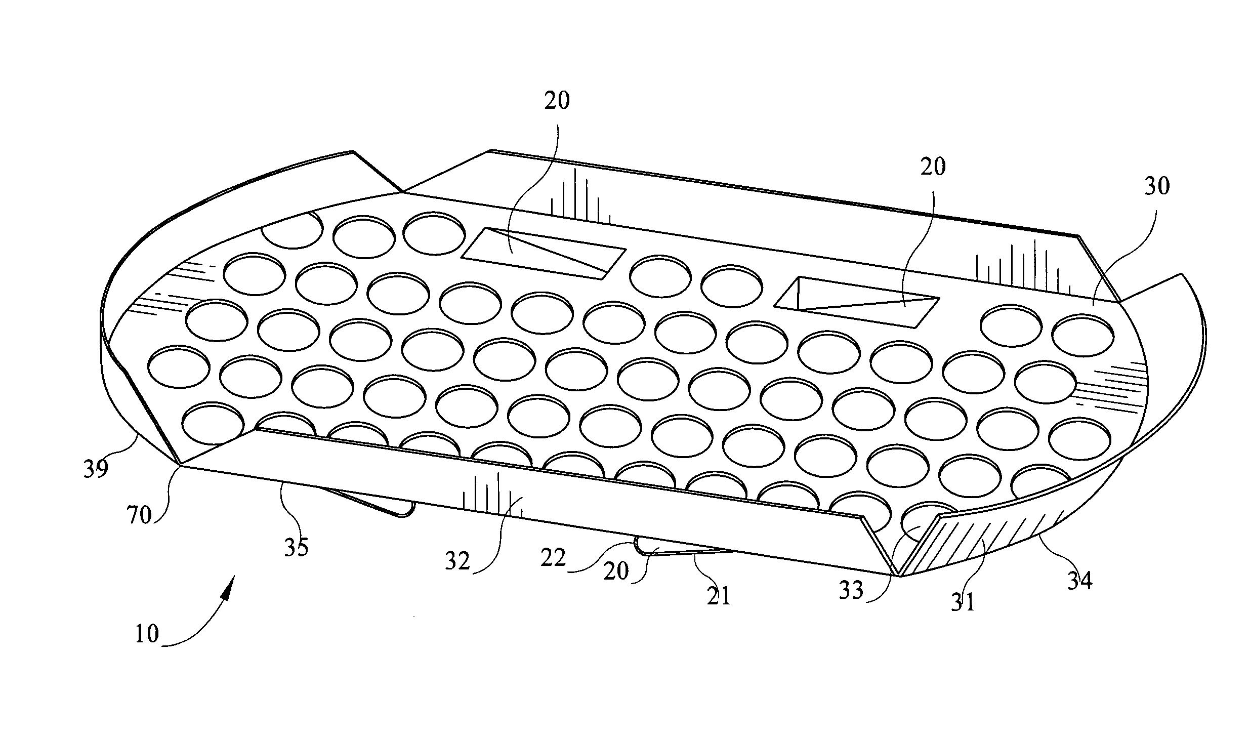
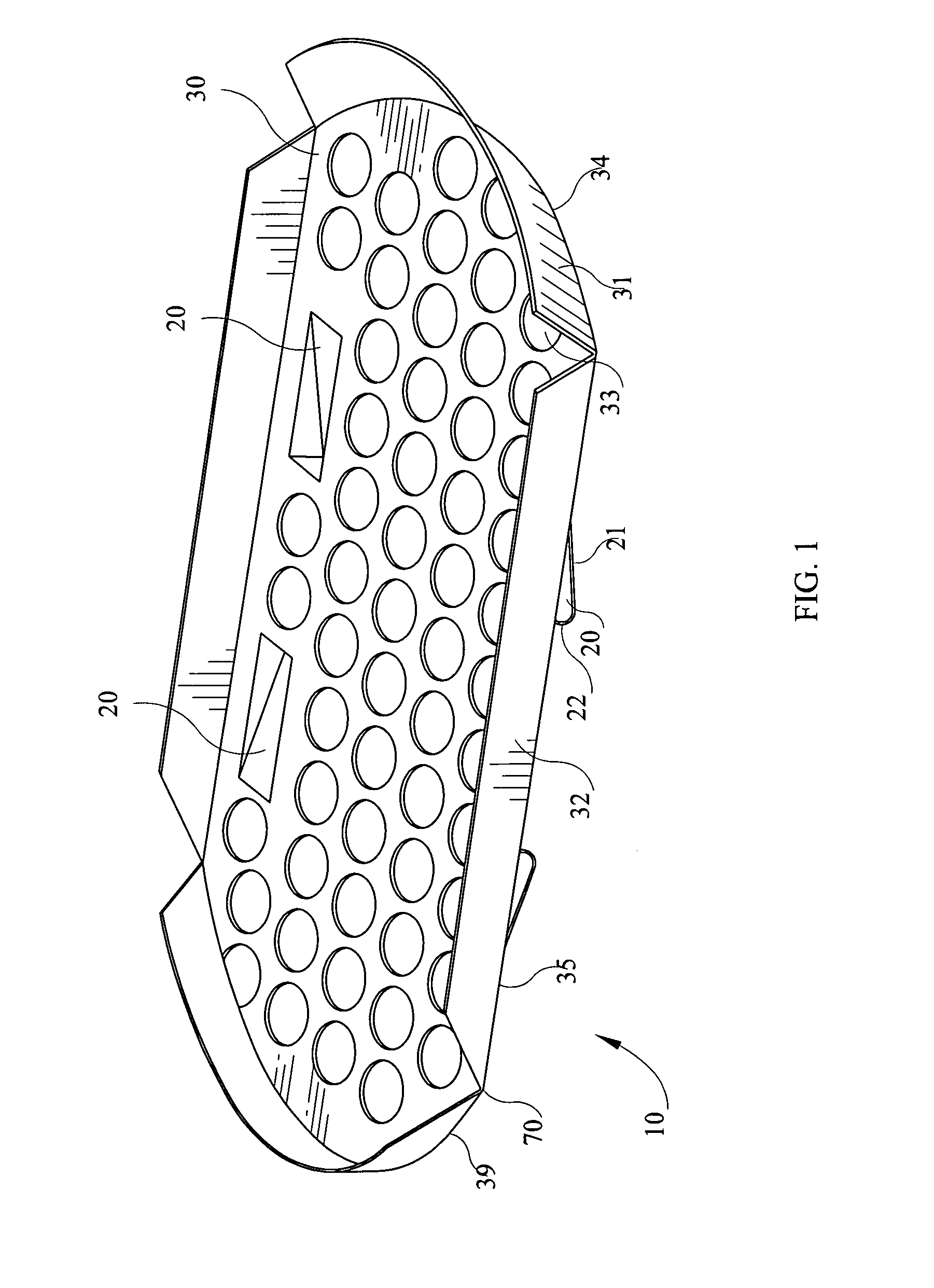
[0007]The present invention addresses the shortcomings of the prior art and provides, among other things, a cooking tray with at least one downward extending member to deter the cooking tray from moving or sliding when received by a cooking rack, and a cooking rack capable of receiving said cooking tray.
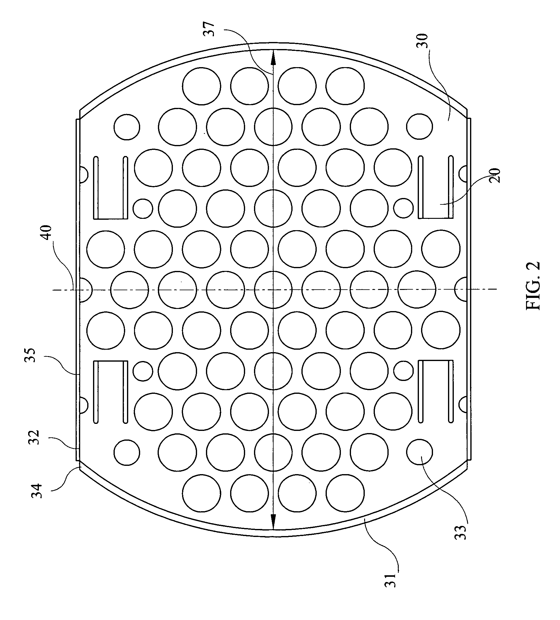
[0008]The cooking tray of the present invention is designed having two lateral straight edges and two convex rounded edges. The shape is essentially that of a circle with two sides cut to form two lateral straight edges. The convex rounded edges provide the maximum cooking space, while the lateral straight edges provide a more efficient use of the space within the presentation pan. By bending the edges of the material composing the planar surface of the cooking tray in an upright and transverse position from the planar surface, a container aspect is provided. Often when products are being cooked by being submerged into cooking vats filled with shortening and other ingredients, the products being cooked have a tendency to float away. The container aspect of the cooking tray provides a greater ability to maintain the products being cooked on the cooking tray.
[0009]The cooking tray incorporates open spaces to allow all cooking ingredients, including shortening and any other cooking ingredients, to reach the products being cooked from all directions to ensure an even cooking. These open spaces can be achieved by either punching holes in a solid material such as, for example, aluminum, or using a wire design for the cooking tray. Ideally, the number of open spaces is maximized to allow the greatest access to the products being cooked, while still maintaining the structural stability of the cooking tray.

Problems solved by technology

Often when products are being cooked by being submerged into cooking vats filled with shortening and other ingredients, the products being cooked have a tendency to float away.

Method used


Image

  • Cooking tray and apparatus for securing cooking tray
  • Cooking tray and apparatus for securing cooking tray
  • Cooking tray and apparatus for securing cooking tray

Examples


first embodiment

[0042]Referring now to FIG. 8-10, the cooking tray 10 is inserted into the cooking rack 50 from the side. In a first embodiment, the cooking rack 50 contains a z-shaped platform 51 approximately 3.2 inches in length 52 and 1.5 inches in width 53 and 1.5 inches in height 55. The cooking tray 10 is inserted into the cooking rack 50 by sliding along the z-shaped platform 51. When inserted, the cooking tray 10 sticks out over the front edge of the cooking rack 50. The cooking tray 10 slides onto the z-shaped platform 51 using the long arm 21 of the downward extending member 20 to facilitate insertion. When the cooking tray 10 reaches the end of the z-shaped platform 51, the cooking tray 10 falls down into place, causing the cooking tray 10 to sit directly on the z-shaped platform 51, being supported along the lateral straight edges 35. The downward extending member 20 nearest the rear of the cooking rack 10 sits abutted to the edge of the z-shaped platform 51. In a preferred embodiment ...

embodiment 50

[0043]As shown in FIG. 8, the cooking rack 50 of this embodiment 50 contains walls 57 along the sides having the z-shaped platforms 51. In this embodiment, the walls 57 are to be produced from a punched aluminum or similar composition to provide vents for the circulation of the cooking ingredients, including shortening and any other cooking ingredients, such that the flow of cooking ingredients may evenly cook the products at an even temperature. The walls 57 of this embodiment should be punched to create a plurality of circular holes to provide for the maximum circulation of cooking ingredients while maintaining the structural integrity of the cooking rack 50.

[0044]In an alternative embodiment, FIG. 11-12 show the cooking rack 150 having a wire 151 strip across the rear vertical support bars 154 approximately 0.2 inches in width. The cooking tray 10 is inserted into the cooking rack 150 by sliding over the wire 151. When inserted, the cooking tray 10 sticks out over the front edge ...


PUM


Abstract

The present invention relates to an apparatus facilitating the cooking of multiple products simultaneously. More particularly, the present invention relates to cooking tray and cooking rack for securing the cooking tray. The cooking tray of the present invention comprises a downward extending member, a planar surface, convex rounded edges, lateral straight edges, convex upward extending surfaces, lateral upward extending surfaces, a transition area, and circulation vents. The cooking tray is inserted into a cooking rack along support bars or a platform and is secured using a downward extending member that is obstructed by a wire or the edge of the platform, deterring the cooking tray from falling or shifting during use. The cooking tray is removable from the cooking rack by lifting the cooking tray up the height of the downward extending member. The cooking tray is made of either a punched aluminum or wire, with circulation vents such that the products being cooked may be cooked evenly.

Description

[0001]This application claims the benefit of U.S. provisional patent application Ser. No. 61 / 188,759, filed Aug. 12, 2008, for cooking tray and apparatus for securing cooking tray.BACKGROUND OF THE INVENTION [0002](a) Field of the Invention[0003]The present invention relates to an apparatus facilitating the cooking of multiple products simultaneously. More particularly, the present invention relates to a cooking tray and cooking rack for securing a cooking tray therein.[0004](b) Background of the Invention[0005]In the field of cooking technology, the opening and cavity in the cookers that receive the cooking tray are typically of circular cross-section. Typically, the same cooking tray is used in the cooker as is used to store the cooked product and later for presenting the cooked product for service to a customer. Typically, multiple cooking trays are placed on a rectangular presentation pan. While, circular cooking trays provide the greater surface area within the cooker upon whic...

Claims


Application Information

Patent Timeline
Patent Type & Authority Patents(United States)
IPC IPC(8): A47J27/00
CPCA47J36/20A47J36/16
Inventor YATES, BARRY G.SHELTON, WINSTON L.
Owner WINSTON IND
Learn More