Firearm laser sight alignment assembly

a laser sight and assembly technology, applied in the field of firearm laser sight alignment assembly, can solve the problems of large number of components, significant deviation of the trajectory of the bullet, and increase the complexity of manufacturing and inventory, and achieve the effect of preventing axial and longitudinal movemen

Active Publication Date: 2014-04-01
CROSMAN CORP
View PDF47 Cites 45 Cited by
  • Summary
  • Abstract
  • Description
  • Claims
  • Application Information

AI Technical Summary

Benefits of technology

[0011]The present disclosure provides a firearm laser sight assembly having a housing engaging a portion of the firearm and a laser module for emitting a beam along an optical axis, the laser module has an outside surface, wherein the outside surface includes an outer seat. The assembly further includes a resilient grommet mechanically engaging the outer seat in a first adhesive free interference fit, wherein the grommet includes an external seat. A laser cover engages the housing to retain the grommet with respect to the housing and the laser cover, wherein each of the laser cover and the housing form a second adhesive free interference fit with the external seat of the grommet to substantially preclude axial and longitudinal movement between the grommet and the laser module.
[0018]The method can further provide that the first interference fit and the second interference fit operably preclude longitudinal and axial movement of the laser module relative to the resilient coupling and housing. Also, the first interference fit and the second interference fit operably can permit angular movement of the laser module relative to the resilient coupling and the housing.
[0021]In one construction, the switch is sized to be accessible from opposing sides of the housing. Thus, the switch can be sized to be accessible from a left and a right side of the firearm. It is also contemplated at least one of, and in certain constructions each of, the frame, the barrel portion and the trigger guard is free of a mounting rail. Alternatively, the housing can be free of a mounting rail, such as a Weaver or Picatinny rail. In a further configuration, the switch can be located forward of the trigger and below the barrel, without requiring the housing to engage a mounting rail.

Problems solved by technology

However, as the laser beam will follow an effectively straight line, and the bullet will follow a ballistic trajectory so that, despite a high muzzle velocity, at long distances the trajectory of the bullet will deviate significantly from the straight line.
However, these prior devices require a significant number of components.
The large number of components adds complexity in manufacturing and inventory.
In addition, the large number of parts, each having an associated tolerance, creates alignment issues with respect to both manufacture and use of the product.

Method used


Image

  • Firearm laser sight alignment assembly
  • Firearm laser sight alignment assembly
  • Firearm laser sight alignment assembly

Examples


Embodiment Construction

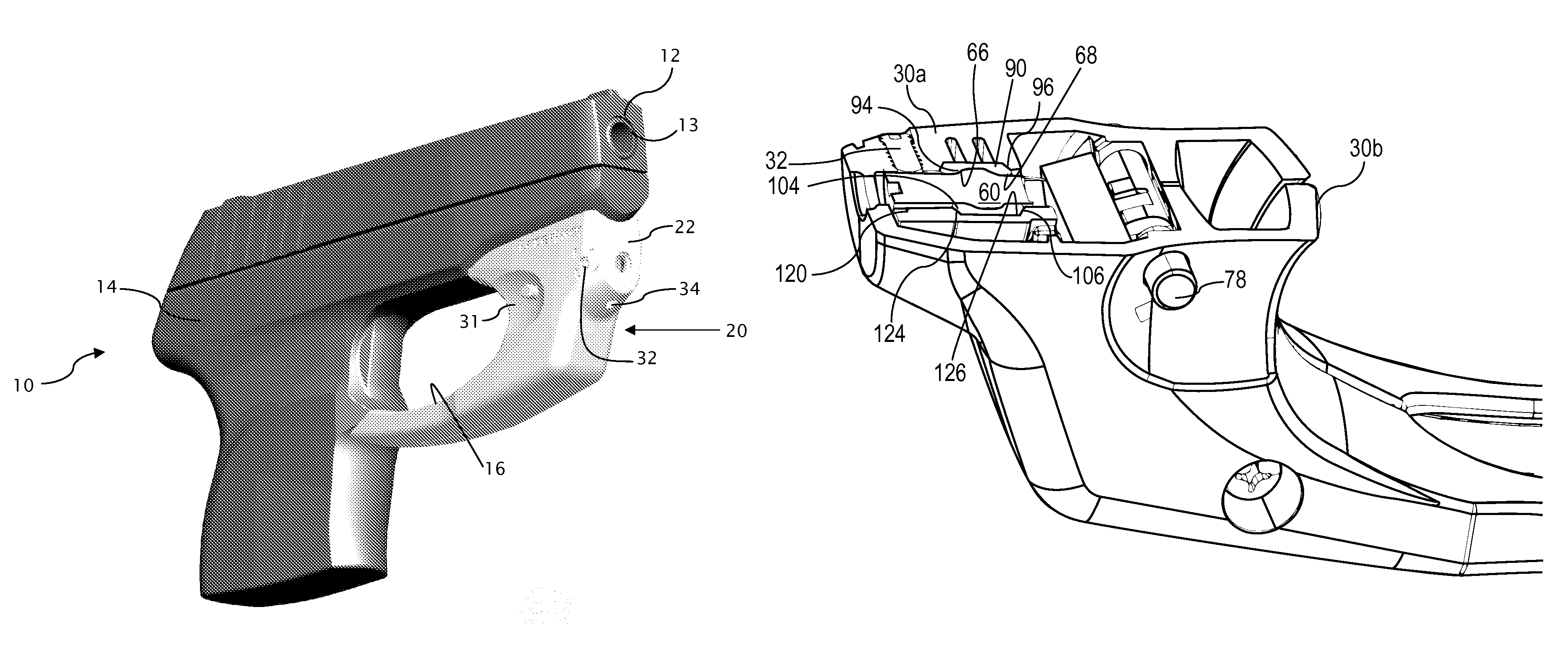
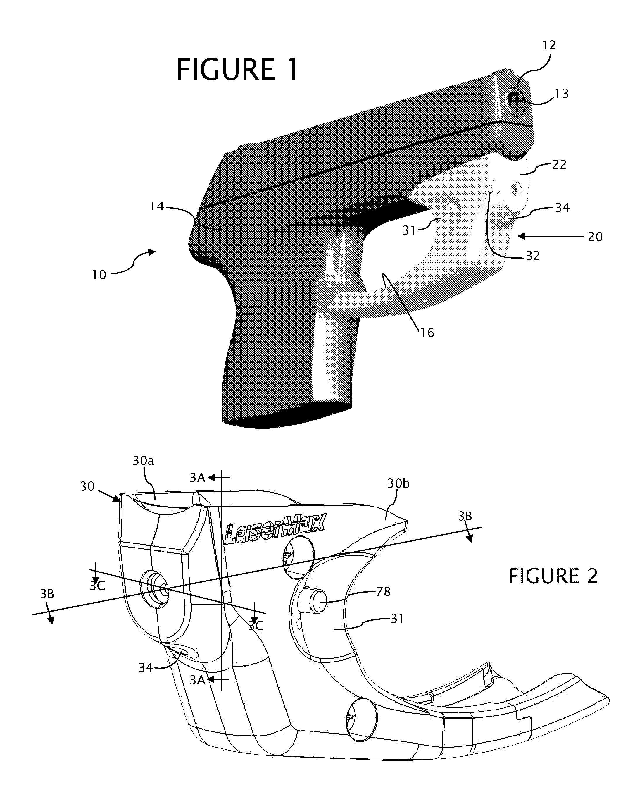
[0054]Referring to FIG. 1, the present firearm laser sight alignment assembly 20 is embodied in a laser sight 22 shown operably engaged with a firearm 10.

[0055]Although the firearm 10 is shown as a hand gun, it is understood the alignment assembly 20 is not limited to use with handguns, but can be employed with any pistol, gun, or rifle that selectively launches a projectile, whether by compressed gas, combustion or electromagnetic actuation. Further, although the assembly 20 is shown in conjunction with a firearm that does not have any mounting rail, it is understood the assembly can be employed with laser sight 22 that engages a mounting rail. The assembly 20 is not limited by the particular laser sight or mechanism for engaging the firearm 10.

[0056]The firearm 10 includes in relevant part a barrel 12, a frame 14, and a trigger guard 16. Although the alignment assembly 20 is shown as engaging the trigger guard 16 of the firearm 10, it is understood the alignment assembly can be co...


PUM

PropertyMeasurementUnit
output poweraaaaaaaaaa
widthaaaaaaaaaa
widthaaaaaaaaaa

Abstract

A firearm laser sight alignment assembly includes a laser module for emitting a beam along an optical axis, the laser module having an outer seat. The alignment assembly encompasses a resilient grommet mechanically engaging the outer seat in a first adhesive free interference fit. The grommet includes an external seat sized to form adhesive free interferences fits with a laser cover and the housing, as the laser cover engages the housing to retain the grommet with respect to the housing and the laser cover. Upon operable assembly, the interference fits substantially preclude axial and longitudinal movement between the grommet and the laser module as well as the grommet and the laser cover and housing, while allowing angular movement of the laser module to a desired alignment position.

Description

CROSS-REFERENCE TO RELATED APPLICATIONS[0001]Not applicable.STATEMENT REGARDING FEDERALLY SPONSORED RESEARCH OR DEVELOPMENT[0002]Not applicable.REFERENCE TO A “SEQUENCE LISTING”[0003]Not applicable.BACKGROUND OF THE INVENTION[0004]1. Field of the Invention[0005]The present disclosure generally relates to sights for firearms and particularly to laser sights for firearms, and more particularly to a firearm laser sight alignment assembly.[0006]2. Description of Related Art[0007]Laser sighting devices for firearms have been used for a number of years. Laser sighting devices use a laser to assist in sighting the firearm. However, as the laser beam will follow an effectively straight line, and the bullet will follow a ballistic trajectory so that, despite a high muzzle velocity, at long distances the trajectory of the bullet will deviate significantly from the straight line. Also, the laser sight must be mounted to the firearm, which means that the laser beam cannot propagate concentric w...

Claims


Application Information

Patent Timeline
Patent Type & Authority Patents(United States)
IPC IPC(8): F41G1/00
CPCF41G1/35G01B11/27F41A19/11F41G1/36Y10T29/49826Y10T29/49895
Inventor KOWALCZYK, JOHNTULLER, JEFFREYMOCK, JEFFREY
Owner CROSMAN CORP
Why Eureka
Try Eureka