Backrest inclination structure for lumbar support

a technology of lumbar support and inclination structure, which is applied in the direction of movable seats, chairs, transportation and packaging, etc., can solve the problems of complicated assembly process, and achieve the effect of reducing chair manufacturing costs, facilitating movement adjustment, and effectively simplifying the inclination mechanism

Inactive Publication Date: 2014-04-15
OASYSCHAIR
View PDF8 Cites 9 Cited by
  • Summary
  • Abstract
  • Description
  • Claims
  • Application Information

AI Technical Summary

Benefits of technology

[0007]A conventional backrest adjustment unit positioned at a chair laterally consists of too many constituent elements and thus renders an assembly process thereof complicated, not to mention that only a portion of a backrest of the chair is in contact with the back of a person sitting on the chair, thanks to the conventional backrest adjustment unit. The present invention overcomes the aforesaid drawbacks of the prior art. According to the present invention, a backrest adjustment mechanism positioned at a chair laterally comprises a spring continuous control unit for limiting the position of a support plate pivotally coupled to a backrest from the rear to enable a sitter on the chair to lift the spring continuous control unit by hand to allow the spring continuous control unit to unlock and enter a free state. Thus, the backrest pivotally coupled to the support plate can be adjusted to a preset position and direction when the backrest comes into contact with the human back and under the weight thereof. After a required back contact position has been attained, the sitter presses the spring continuous control unit by hand to allow the spring continuous control unit to return to a locked state and then position precisely the backrest pivotally coupled to the support plate. Thus, the human back can come into tight contact with the adjusted backrest. Hence, the backrest adjustment mechanism is effectively simplified and thus enhances the comfort given to the sitter.
[0009]A sitter on the chair lifts the spring continuous control unit by hand to enable the spring continuous control unit to unlock and enter a free state and thereby enable the backrest adjustment mechanism to drive controllably the backrest to perform directional adjustment. Thus, the backrest pivotally coupled to the support plate undergoes preset directional adjustment as soon as the backrest comes into contact with a human back under a weight thereof. After a required back contact position has been attained, the sitter presses the spring continuous control unit by hand to allow the spring continuous control unit to return to a locked state and then position precisely the backrest pivotally coupled to the support plate. Thus, the human back can come into tight contact with the adjusted backrest. Alternatively, the sitter lifts the spring continuous control unit by hand to enable the spring continuous control unit to enter a free state in a manner that the backrest undergoes seamless displacement along with the human back to give comfort to the sitter and protect the sitter against lumbago and kyphosis which are common among sedentary individuals, not to mention that the backrest adjustment mechanism is effectively simplified and thus cuts chair manufacturing costs.
[0010]Another objective of the present invention is to provide a backrest inclination structure for lumbar support, comprising a backrest adjustment mechanism positioned at a chair laterally. The backrest adjustment mechanism is provided with covering plates corresponding in shape thereto and pressing against the support plate coupled to the backrest from the front and rear to cover a bottom and the hollow tubes of the support plate directionally with upper and lower ends of the front and rear covering plates and to fix the front and rear covering plates to preset positions of the support plate with screwing elements such that the support plate pivotally coupled to the backrest has an aesthetic appearance.
[0011]Yet another objective of the present invention is to provide a backrest inclination structure for lumbar support, comprising a backrest adjustment mechanism positioned at a chair laterally. The backrest adjustment mechanism is provided with covering plates pressing against the support plate coupled to the backrest from the front and rear. Through holes corresponding in position to the connection tube of the backrest and the two hollow tubes of the support plate are formed in the front covering plate to facilitate adjustment of movement between the support plate and the backrest. A hollowed-out zone is formed at the lower end of the rear covering plate to allow screwing elements to lock together the support plate and the support-connection portion on the rear side of the spring continuous control unit when the lower end of the support plate is covered, or to facilitate subsequent removal of the screwing elements. Protruding portions spaced apart from each other protrude from the bottom of the rear covering plate and insert into apertures of the plate, respectively, as soon as an L-shape plate abuts against the hollowed-out zone, such that the rear covering plate has an aesthetic appearance.

Problems solved by technology

A conventional backrest adjustment unit positioned at a chair laterally consists of too many constituent elements and thus renders an assembly process thereof complicated, not to mention that only a portion of a backrest of the chair is in contact with the back of a person sitting on the chair, thanks to the conventional backrest adjustment unit.

Method used


Image

  • Backrest inclination structure for lumbar support
  • Backrest inclination structure for lumbar support
  • Backrest inclination structure for lumbar support

Examples


Embodiment Construction

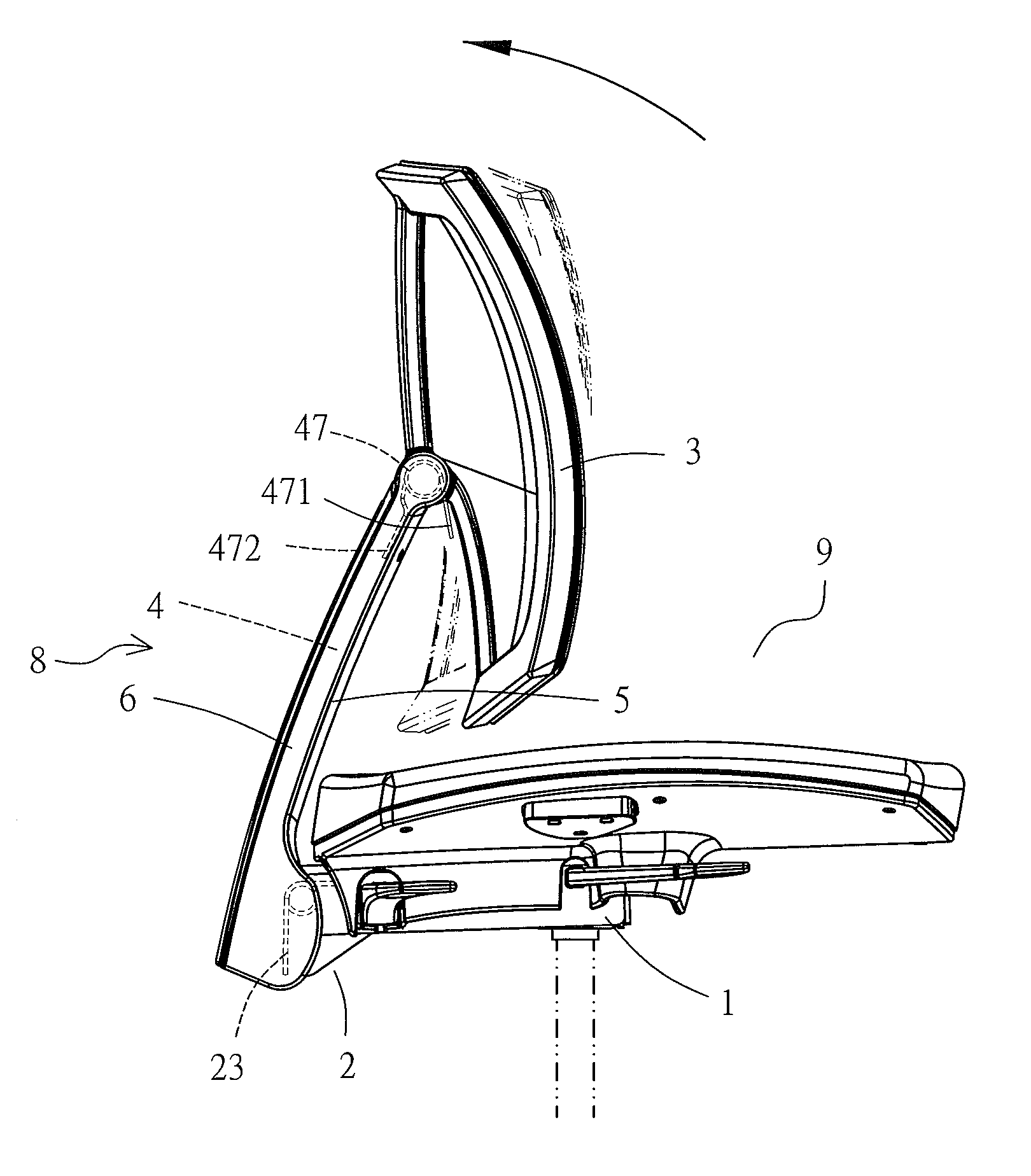
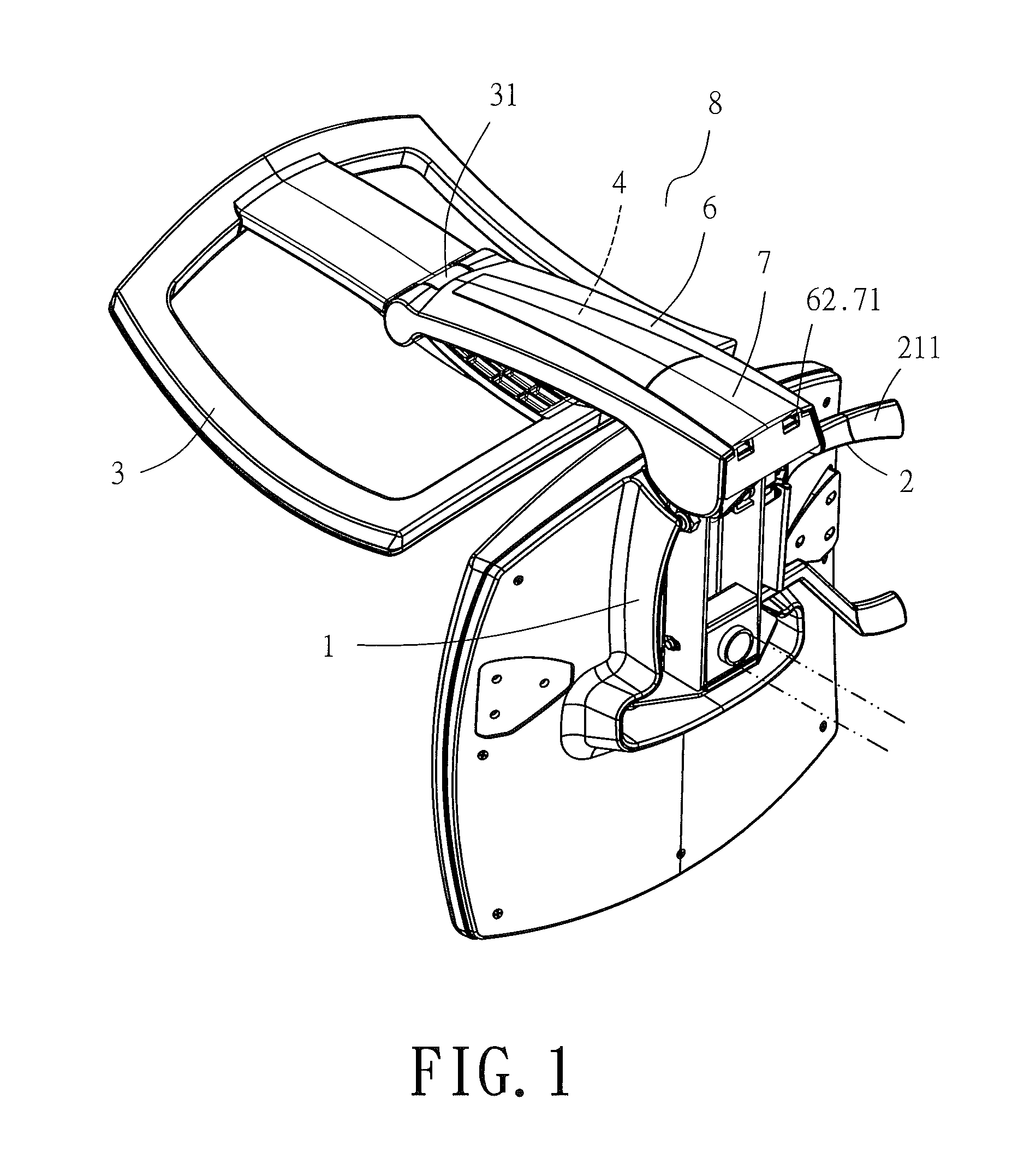
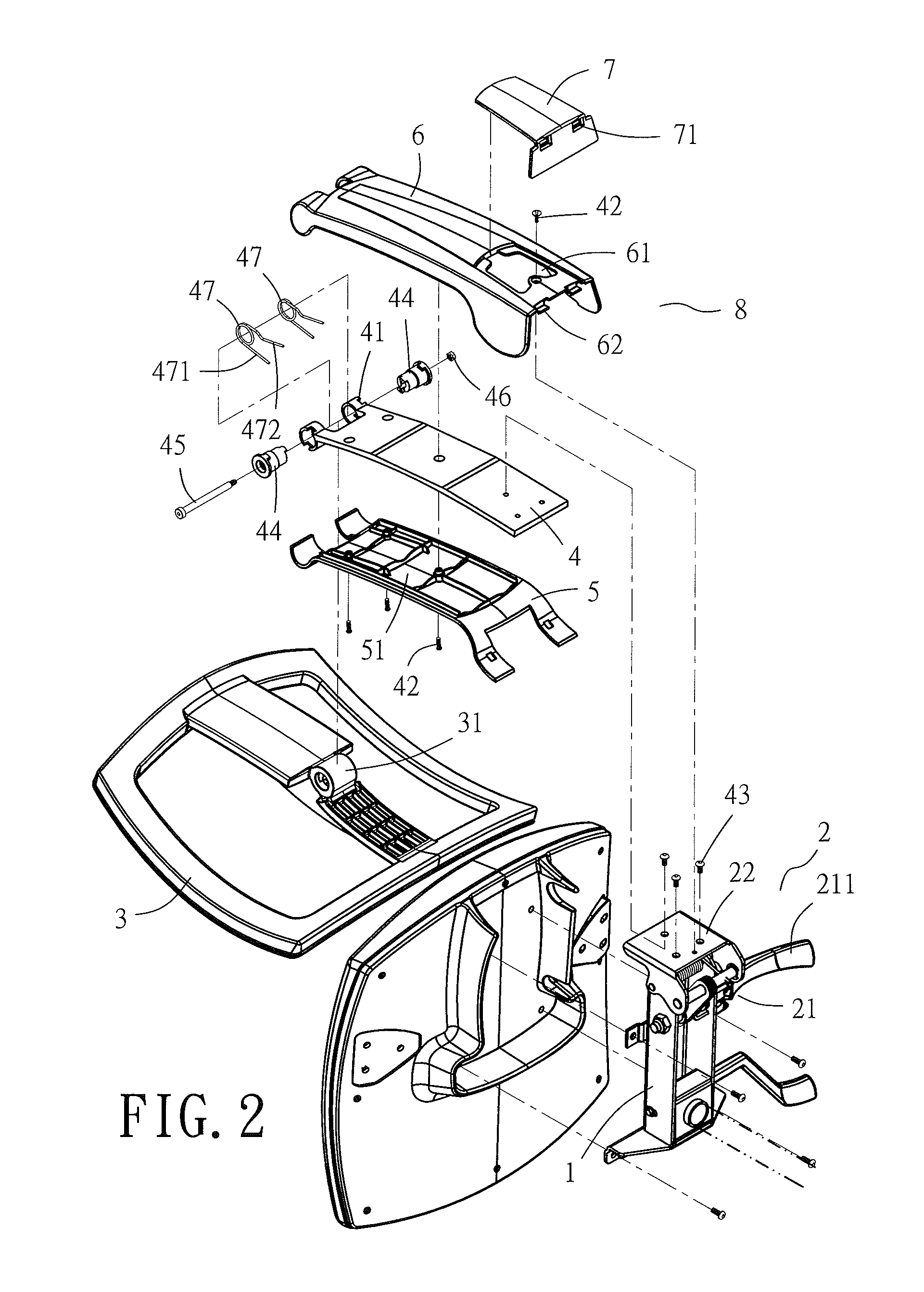
[0018]Referring to FIGS. 2, 3, the present invention provides a backrest inclination structure for lumbar support. As shown in the diagrams, the backrest inclination structure for lumbar support has a backrest adjustment mechanism 8 positioned at a chair 9 laterally. The backrest inclination structure further comprising has a spring continuous control unit 2 disposed at the end of a butterfly-shaped mounting member 1 at the bottom of a chair. The spring continuous control unit 2 comprises a control lever 21 penetrating and straddling the end of the butterfly-shaped mounting member 1, a support-connection portion 22 pivotally coupled to the end of the butterfly-shaped mounting member 1, and a linking spring 23 with one end abutting against the inner side of the support-connection portion 22. Referring to FIG. 2, due to the distance Y shown in FIG. 3, a spring 212 disposed at a lever 211 beside the control lever 21 is prevented from being compressed excessively to stick outward while ...


PUM


Abstract

A backrest inclination structure for lumbar support enables a backrest to enter a free state when a user sitting at any position of a chair lifts a lever of a spring continuous control unit, such that the backrest fits the user's moving back when the backrest is configured for movable inclination. Hence, the backrest can move together with the user's back ergonomically to provide lumbar support. Accordingly, the user can sit comfortably on the chair and be free from lumbago and kyphosis which are common among sedentary individuals.

Description

BACKGROUND OF THE INVENTION[0001]1. Technical Field[0002]The present invention relates to backrest inclination structures for lumbar support and, more particularly, to a backrest inclination structure providing lumbar support and operating in conjunction with a backrest adjustment mechanism positioned at a chair laterally. When in use, the backrest inclination structure can be operated easily to adjust a backrest of the chair and can attain the most comfortable position of the backrest by pressing the human back against the backrest under the weight of the human back. Furthermore, the backrest inclination structure not only enables the human back to conic into tight contact with the adjusted backrest, but also enables the backrest adjustment mechanism to be fixed in place again, thereby simplifying the backrest adjustment assembly and enhancing the comfort provided by the backrest.[0003]2. Description of Related Art[0004]To enable existing chairs to provide maximum comfort to sitter...

Claims


Application Information

Patent Timeline
Patent Type & Authority Patents(United States)
IPC IPC(8): A47C1/024A47C7/40
CPCA47C7/443A47C7/444
Inventor PAN, TUNG-CHUN
Owner OASYSCHAIR
Why Eureka
Try Eureka