
Pistol barrel system and method

a barrel system and pistol technology, applied in the field of interchangeable barrel systems and methods for pistols, can solve the problems of limiting the ability to customize the aesthetic appearance of the pistol, adding to the total weight of the pistol, etc., and achieve the effect of preventing relative rotation

Active Publication Date: 2014-04-22
STURM RUGER & CO INC
View PDF82 Cites 20 Cited by
  • Summary
  • Abstract
  • Description
  • Claims
  • Application Information

AI Technical Summary

Benefits of technology

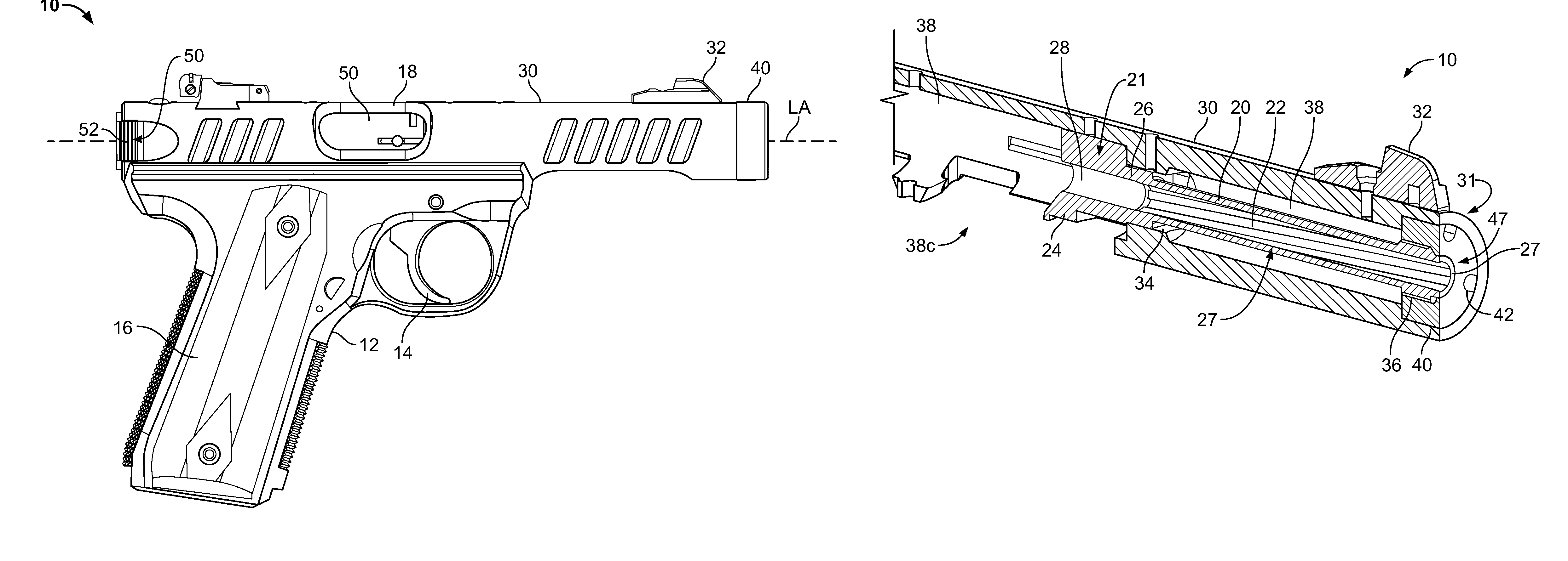
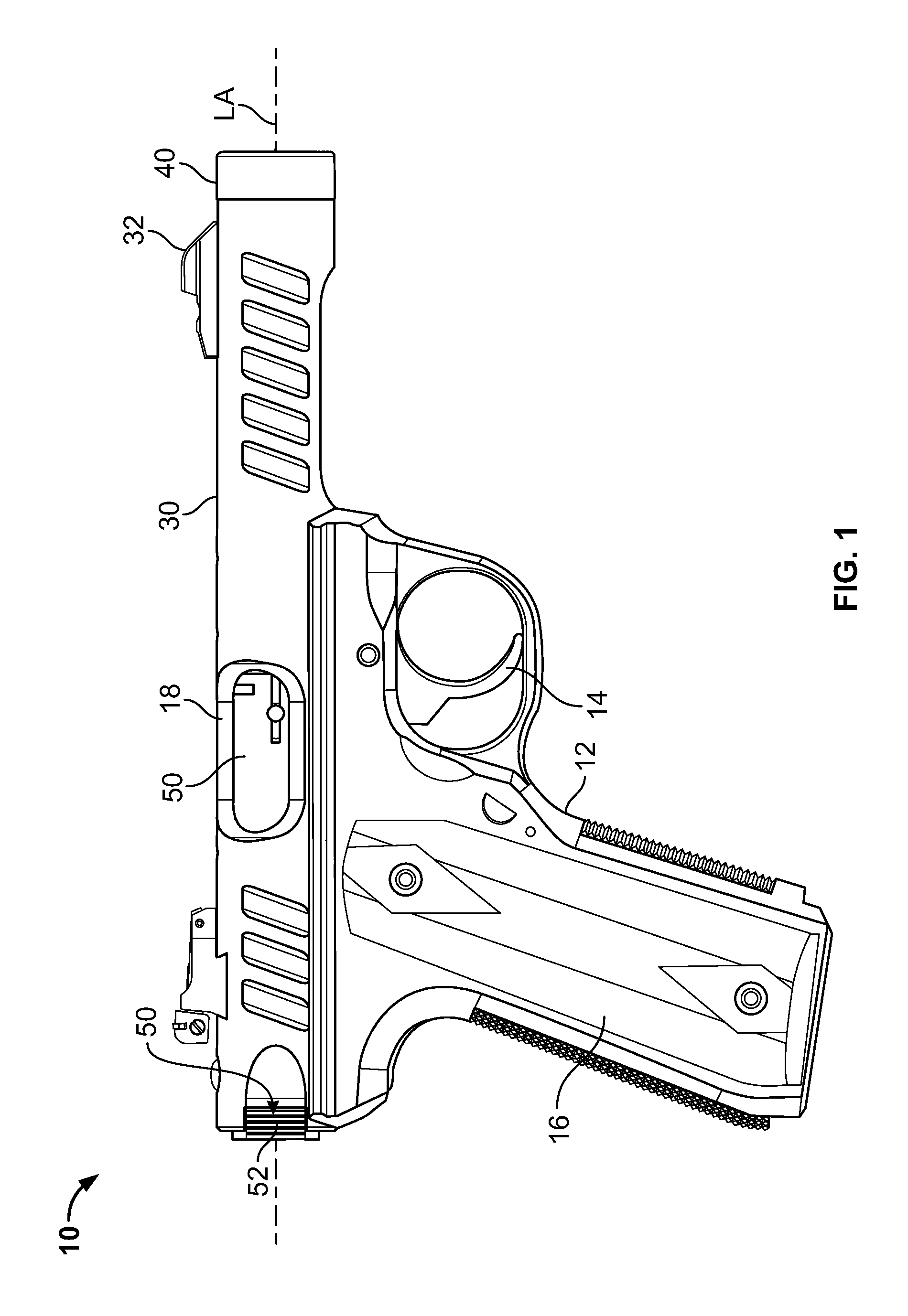
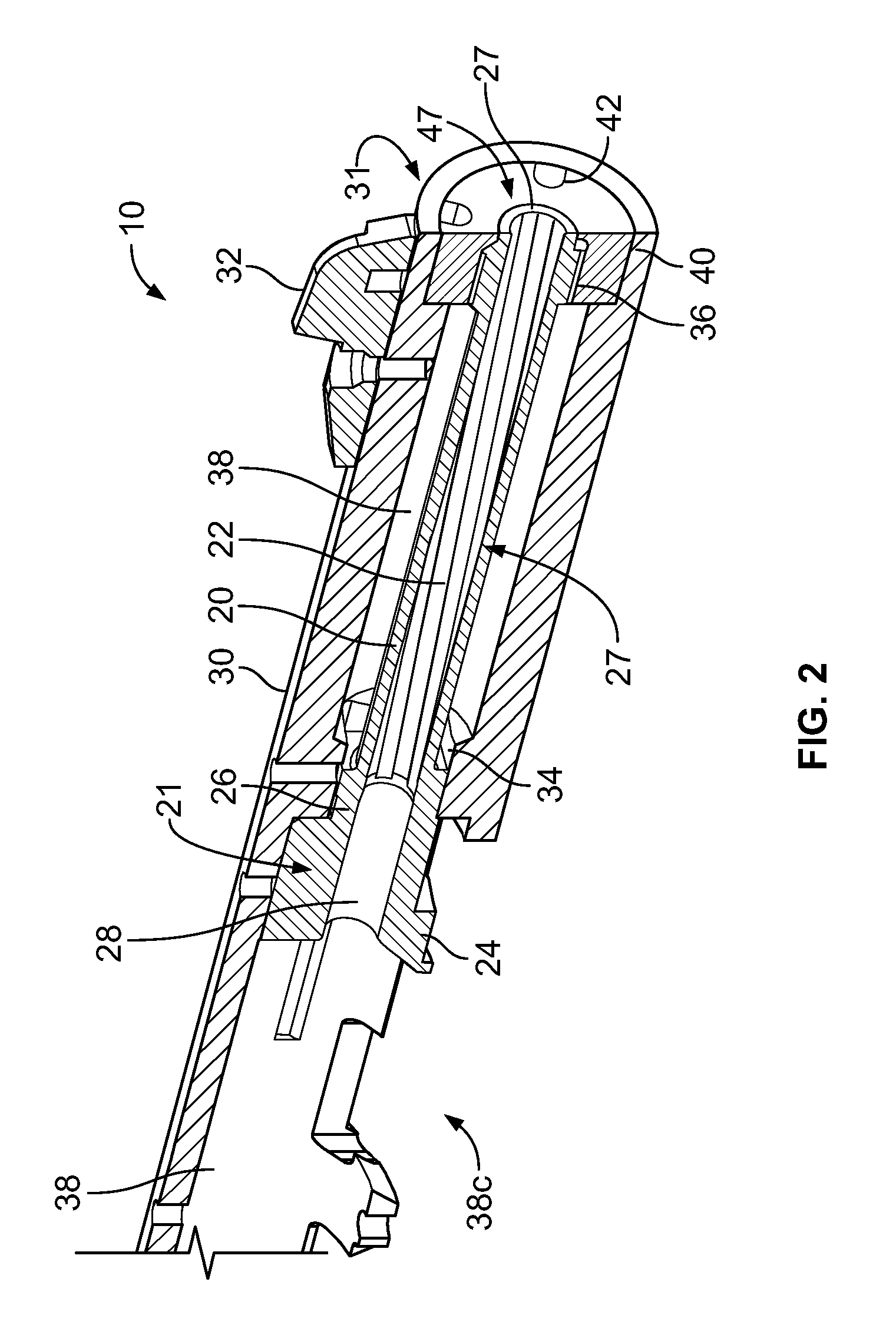
[0006]A barrel system for a firearm such as a pistol according to embodiments of the present disclosure provides a light-weight barrel-receiver assembly. In some embodiments, for example without limitation, an outer aluminum receiver is combined with an inner durable steel barrel insert which is removably mounted thereto. In some embodiments, the barrel insert may be structurally self-supporting independent of the receiver to withstand combustion forces as opposed to merely a thin steel liner or cladding applied to an outer barrel sleeve or receiver constructed of a relatively softer, less durable metal such as aluminum incapable of withstanding combustion forces from discharging the pistol. This advantageously allows the barrel insert to be readily replaced and / or interchanged with other types of inserts while retaining the original receiver. In addition, this interchangeable barrel system allows a user to switch receivers of different types, lengths, and configurations while merely transferring the barrel insert to various receivers. Conversely, the user may retain the same receiver and switch out barrel inserts to different types, lengths, configurations, and chambering to allow different caliber ammunition to be fired from the same pistol-receiver combination by merely swapping barrel inserts. For example, in one embodiment the receiver may be configured and dimensioned for retaining barrel inserts capable of firing either 0.22 or 0.45 caliber cartridges by swapping or switching differently configured and constructed barrel inserts thereby providing a versatile pistol platform suitable for firing multiple size cartridges.
[0007]Embodiments of the barrel system include an anti-rotation device for preventing rotation of the barrel insert with respect to the receiver and a locking member for releasably mounting and securing the barrel insert at least partially inside the receiver. In one embodiment, the anti-rotation device is comprised of an anti-rotation protrusion formed on the barrel insert and a complementary configured and mating recess or socket formed in the receiver for receiving the protrusion.
[0011]A method for assembling a barrel system for a pistol is provided. In one embodiment, the method includes: providing an elongated barrel insert including a rear portion defining a chamber configured for holding a cartridge, a front muzzle end, and a forward muzzle portion having a bore defining a longitudinal axis and bullet pathway; axially inserting the barrel insert into a receiver; axially engaging an anti-rotation protrusion on the barrel insert with a complementary configured socket in the receiver, the protrusion preventing relative rotation between the barrel insert and the receiver; and locking the barrel insert into the receiver. In one embodiment, the inserting step is performed by axially inserting the front muzzle end of the barrel insert through a rear opening of the receiver into an internal cavity disposed inside the receiver. In various embodiments, the locking step includes threadably engaging a barrel cap with the forward muzzle portion of the barrel insert through an open front end of the receiver, and axially drawing the barrel insert forward by rotating the barrel cap. Rotating the barrel cap tightens engagement between a forward facing surface of the barrel insert and rear facing surface of the receiver to secure the barrel insert in the receiver.

Problems solved by technology

However, steel is heavier than some metals such as aluminum often used for other firearm components thereby adding to the total weight of the pistol.
In addition, the use of exposed steel barrels may limit the ability to customize the aesthetic appearance of the pistol.

Method used


Image

  • Pistol barrel system and method
  • Pistol barrel system and method
  • Pistol barrel system and method

Examples


Embodiment Construction

[0036]The features and benefits of the invention are illustrated and described herein by reference to exemplary embodiments. This description of exemplary embodiments is intended to be read in connection with the accompanying drawings, which are to be considered part of the entire written description. In the description of embodiments disclosed herein, any reference to direction or orientation is merely intended for convenience of description and is not intended in any way to limit the scope of the present invention. Relative terms such as “lower,”“upper,”“horizontal,”“vertical,”, “above,”“below,”“up,”“down,”“top” and “bottom” as well as derivative thereof (e.g., “horizontally,”“downwardly,”“upwardly,” etc.) should be construed to refer to the orientation as then described or as shown in the drawing under discussion. These relative terms are for convenience of description only and do not require that the apparatus be constructed or operated in a particular orientation. Terms such as...


PUM


Abstract

An interchangeable barrel system and related method for a pistol includes a barrel insert having an anti-rotation protrusion and a receiver having a complementary configured socket configured for receiving the protrusion. An embodiment of a barrel insert includes a chamber for holding a cartridge and a locking mechanism configured for releasably securing the barrel insert to the receiver. In some embodiments, the locking mechanism comprises a threaded engagement between the barrel insert and receiver. The system allows barrel inserts of different calibers, configurations, and materials to be swapped with the receiver, and vice-versa.

Description

CROSS-REFERENCE TO RELATED APPLICATIONS[0001]The present application claims priority to commonly owned U.S. Provisional Application No. 61 / 568,449 filed Dec. 8, 2011, the entire contents of which are incorporated herein by reference in its entirety.BACKGROUND OF THE DISCLOSURE[0002]The present disclosure generally relates to firearms, and more particularly to an interchangeable barrel system and method for pistols.[0003]Semi-automatic pistols generally include a frame having a grip portion for grasping by the user, barrel defining a chamber for holding a cartridge, trigger-actuated firing mechanism for cocking and releasing a striker or hammer to detonate the cartridge, and an axially reciprocating bolt. The bolt defines a breach block for forming an openable and closeable breech with the rear of the chamber as well known to those skilled in the art.[0004]Barrels, which functionally are pressure vessels, are typically made of a durable and strong material such as steel to withstand ...

Claims


Application Information

Patent Timeline
Patent Type & Authority Patents(United States)
IPC IPC(8): F41A21/00
CPCF41A21/482F41A21/488F41A21/10
Inventor ZONSHINE, AMIR
Owner STURM RUGER & CO INC
Learn More