
Powered rocking bed device

a bed and rocking technology, applied in the field of powered rocking bed devices, can solve the problems of not being conducive to sound sleep, pressure hot spots may develop along the sleeper's body, and the firmness of firm and flat mattresses are not very good at disturbing the body's weigh

Active Publication Date: 2014-04-29
FLEMISTER JAMES
View PDF7 Cites 15 Cited by
  • Summary
  • Abstract
  • Description
  • Claims
  • Application Information

AI Technical Summary

Benefits of technology

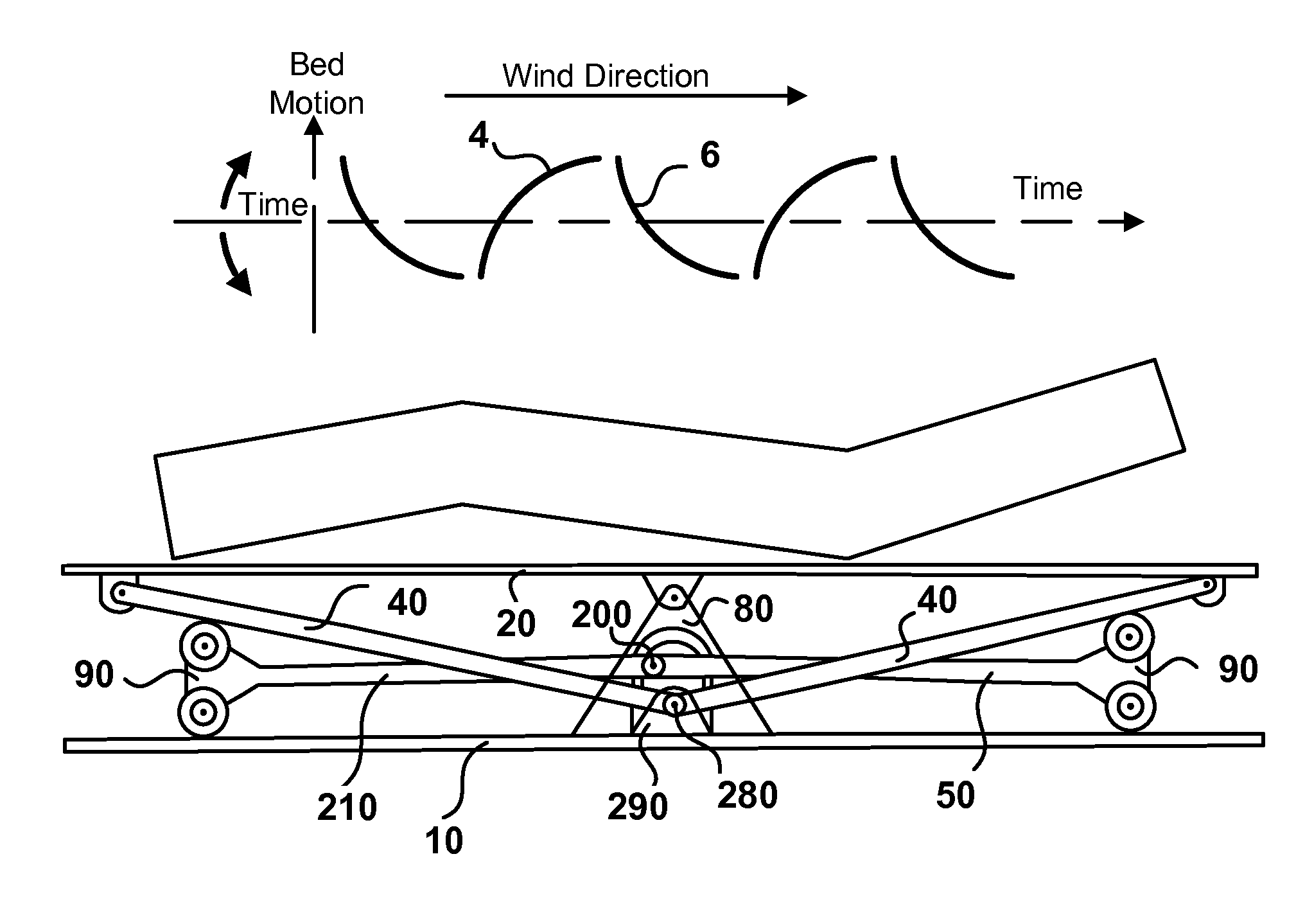
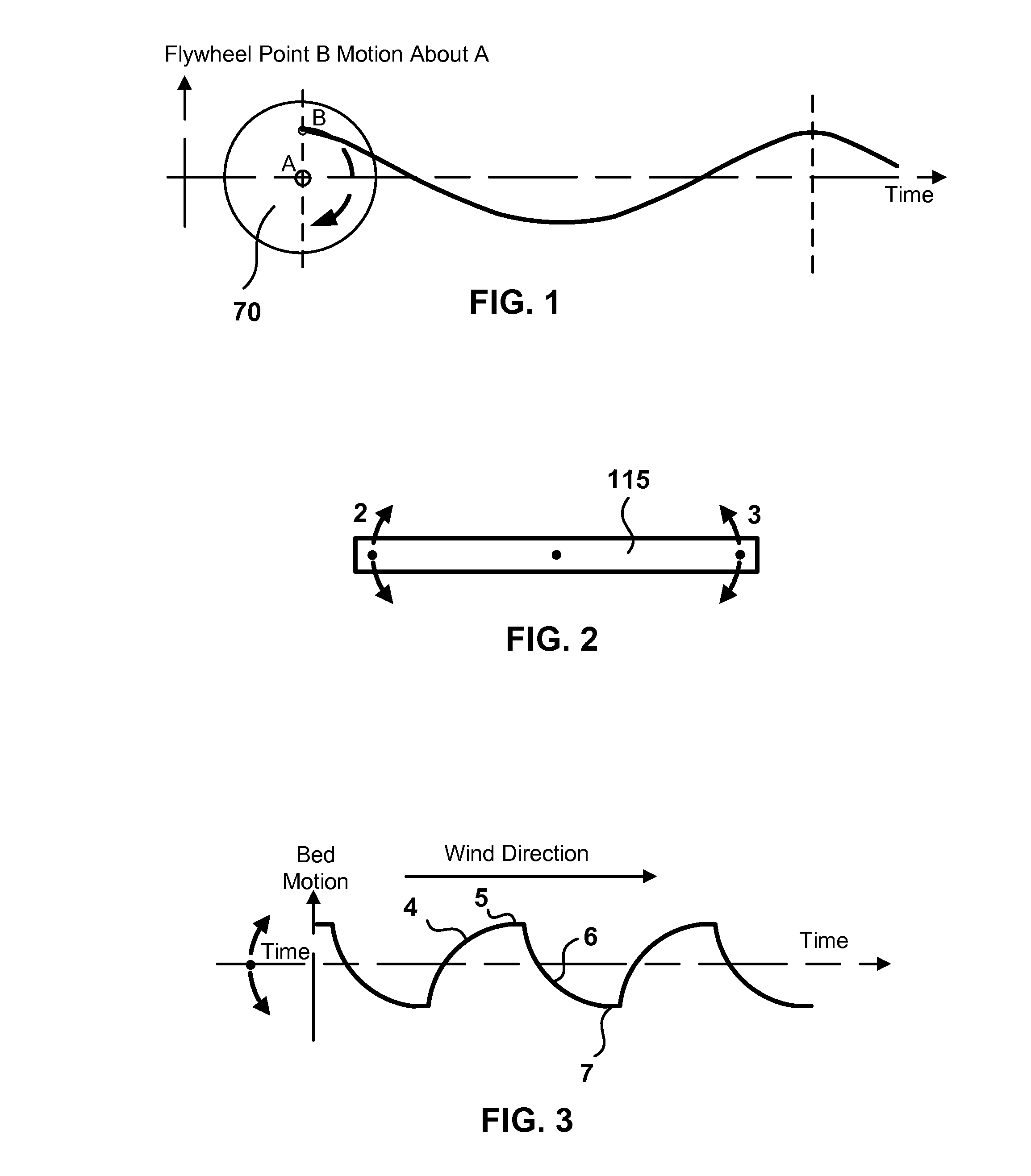
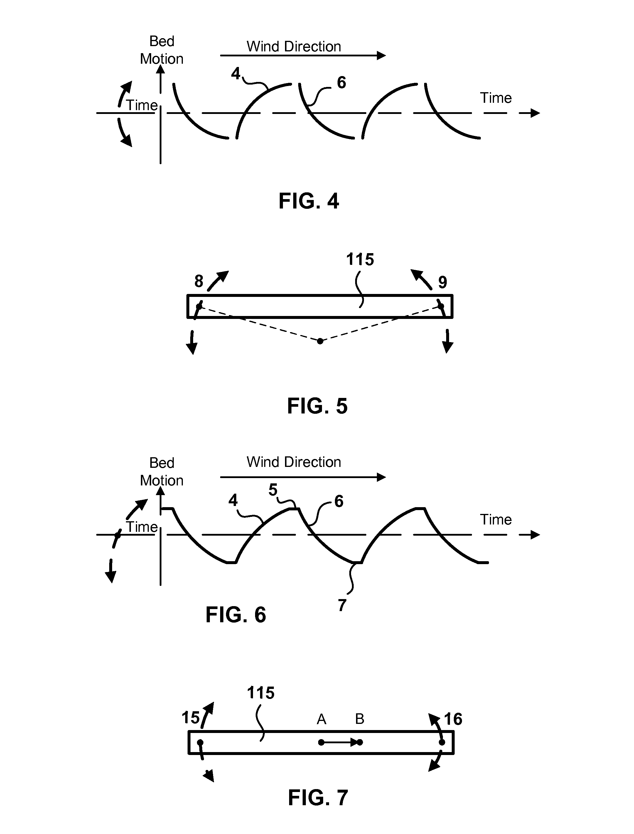
The patent describes a powered rocking bed that moves in a unique wave motion that resembles an ocean wave. The bed has a body support member that is connected to a pivot and a driver, which causes the bed to move in a longitudinally complementary crescent-shaped wave motion. The bed also has a push-pull rod that provides an oscillating push-pull force, which is translated into an oscillating vertical force at the end of the bed. This unique wave motion creates a comfortable and relaxing rocking motion for the bed.

Problems solved by technology

Conventional firm and flat mattresses may not be very good at disturbing the body's weight and as a result, pressure hot spots may develop along a sleeper's body.
This, obviously, is not conducive to sound sleep.
Sleepers with these conditions experience difficulty initiating or maintaining sleep, often resulting in impaired daytime functioning.
Additionally, more than 100 million Americans are, by definition, chronically sleep-deprived.
Doctors know that people without enough movement, or who are bed-ridden, may quickly develop serious health problems.
Reduced oxygen to the cells may therefore result in chronic pain, suffering and disease.
There are hundreds of inventive ideas in the prior art dealing with the improvement of the sleep surface but none have been found that seek to move the mattress in ways that preclude a sleeper from having to reposition themselves during sleep and offer therapeutic benefits at the same time.

Method used


Image

  • Powered rocking bed device
  • Powered rocking bed device
  • Powered rocking bed device

Examples


Embodiment Construction

[0050]Reference will now be made to exemplary embodiments illustrated in the drawings and specific language will be used herein to describe the same. It will nevertheless be understood that no limitation of the scope of the disclosure is thereby intended. Alterations and further modifications of the inventive features illustrated herein and additional applications of the principles of the inventions as illustrated herein, which would occur to one skilled in the relevant art and having possession of this disclosure, are to be considered within the scope of the invention.

[0051]Throughout the present disclosure, the term ‘sleeper’ may refer to a person, pet, animal and any other living thing in a somnambulistic state. The term ‘bed’ may refer throughout to at least one of a mattress, a box spring or mattress support and to both the mattress and the support as a bedding unit. Also the terms fore and aft are used synonymously with the respective terms head and foot in the present disclos...


PUM


Abstract

A powered rocking bed comprises a body support member connected to at least one stationary pivot disposed there beneath and connected via at least one driving linkage to an oscillating powered driver also there beneath, the driving linkage and the pivot configured to move both a head-end and a foot-end of the body support member in a longitudinally complementary oscillating crescent-shaped wave motion comprising a rising convex wave followed by a falling concave wave and inertial transitions there between. The crescent-shaped inertial wave motion is configured to resemble an ocean wave based on a wind blowing across the rising convex wave. A predetermined distance of the stationary pivot from the supporting structure may determine a slope of both the convex and the concave wave motion. The slope may be maximized based on the pivot located in a plane with the body support member and flattened located at a distance therefrom.

Description

CROSS-REFERENCE TO RELATED APPLICATIONS[0001]This application claims the benefit of the priority date of earlier filed U.S. Non-Provisional patent application Ser. No. 13 / 542,750, filed Jul. 6, 2012 for James Flemister and U.S. Provisional Patent Application Ser. No. 61 / 505,488, filed Jul. 7, 2011 and U.S. Provisional Patent Application Ser. No. 61 / 547,215 filed Oct. 14, 2011 also for James Flemister, each incorporated herein by reference in its entirety.BACKGROUND AND FIELD OF INVENTION[0002]Conventional firm and flat mattresses may not be very good at disturbing the body's weight and as a result, pressure hot spots may develop along a sleeper's body. Sleepers may toss and turn from one position to another, mainly to relieve these pressure points, which occur at various places along the body where one comes into contact with a mattress. If these pressure points could be alleviated or removed all together then a sleeper may be able to avoid tossing and turning during sleep and stay ...

Claims


Application Information

Patent Timeline
Patent Type & Authority Patents(United States)
IPC IPC(8): A61G7/10
CPCA61G7/005A61G7/10A47C21/006A61H2201/0142A61H23/02
Inventor FLEMISTER, JAMES
Owner FLEMISTER JAMES
Learn More