
Large deflection constrained insulation displacement terminal and connector

a technology of displacement terminal and connector, which is applied in the direction of securing/insulating coupling contact members, contact members penetrating/cutting insulation/cable strands, electrical equipment, etc., can solve the problem of varying the force applied by the edges, the sharp corners of the inner edges of the fingers and the inability to accommodate a very narrow range of wire sizes

Active Publication Date: 2014-04-29
INTERPLEX IND
View PDF13 Cites 14 Cited by
  • Summary
  • Abstract
  • Description
  • Claims
  • Application Information

AI Technical Summary

Benefits of technology

The solution enables reliable and consistent electrical contact over a wider range of wire sizes and under varying conditions, enhancing the durability and performance of IDCs by reducing the impact of temperature and dimensional variations.

Problems solved by technology

Consequently, the distance between the inner edges of fingers that engage the wire can only accommodate a very narrow range of wire sizes.
As are result of the stamping operation employed in the manufacture of typical IDTs, the corners of inner edges of the fingers are sharp and the opposing inner edges are uneven.
The sharpened corners of the inner edge cut into the wire during the installation of the wire in an IDC and the uneven inner edges result in varying forces being applied by the edges to the wire along the inner edges.
The structure of such inner edges in conventional IDTs can result in intermittent or unreliable connections between the IDT and the wire over time.
Moreover, temperature cycling or variations with typical IDCs can result in a varying resistance between the IDT and a wire disposed within the IDT as the pressure applied to the wire by interior terminal edges varies.
Consequently, in IDCs carrying large currents, significant increases in heat can result in circumstances in which the resistance between the terminal and the wire increases.

Method used


Image

  • Large deflection constrained insulation displacement terminal and connector
  • Large deflection constrained insulation displacement terminal and connector
  • Large deflection constrained insulation displacement terminal and connector

Examples


Embodiment Construction

[0025]The entire disclosure of U.S. Provisional Patent Application No. 61 / 534,448 filed Sep. 14, 2011 and titled Large Deflection High Normal Force Constrained Insulation Displacement Terminal is hereby incorporated by reference.

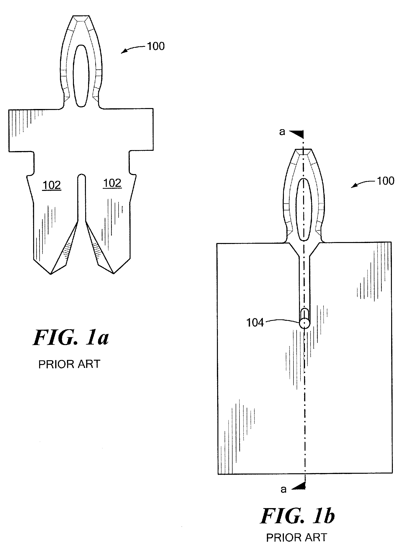
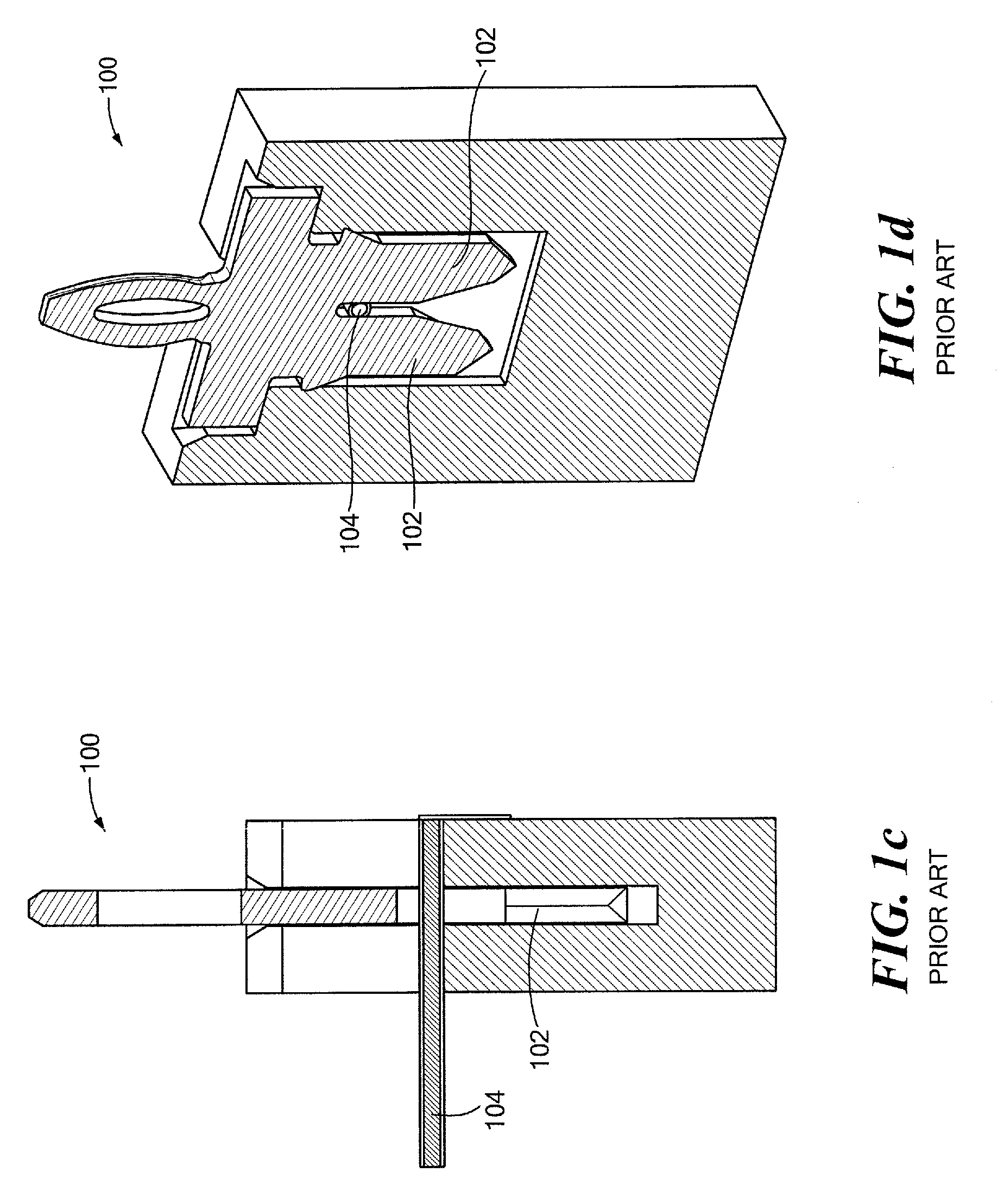
[0026]A prior art insulation displacement connector (IDC) employing an insulation displacement terminal (IDT) is illustrated in FIG. 1a-1d. The IDT 100 includes fingers 102 of generally constant width along the length of the fingers. The fingers are relatively stiff and permit little outward deflection due to the finger 102 stiffness in a direction transverse to the length of the fingers. Consequently, at the point of engagement of fingers 102 with a wire 104 disposed therebetween the conventional IDT can only accommodate a very narrow range of wire sizes.

[0027]As illustrated in FIG. 1d, conventional IDTs have a base portion, a contact portion that extends from one side of the base portion and a pair of spaced fingers that extend from the opposing side of th...


PUM


Abstract

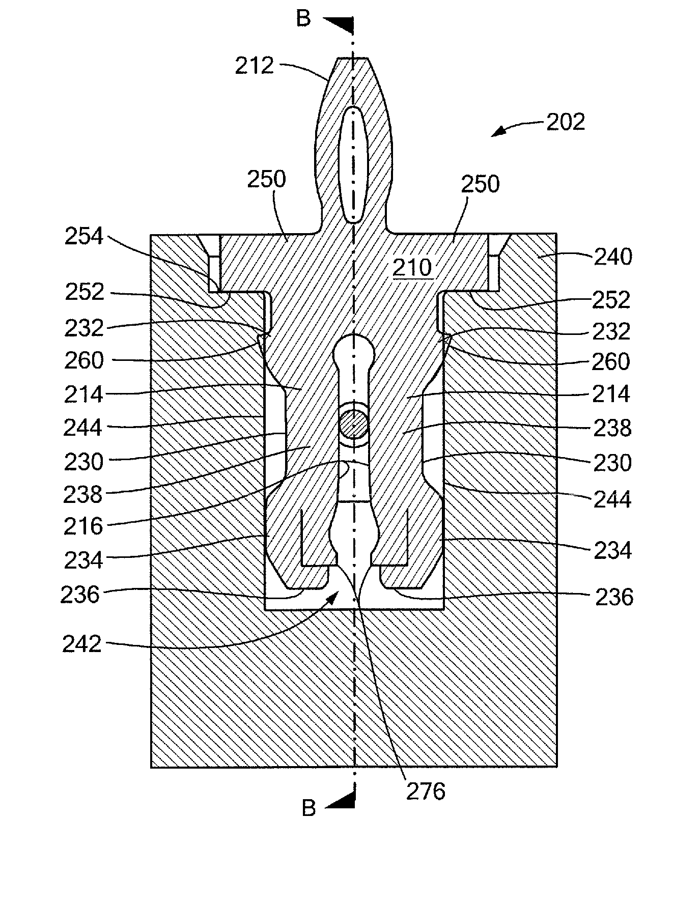
An improved insulation displacement terminal (IDT) includes opposed spaced fingers having outer edges with first and second abutment sections adjacent the ends of the outer edges. A resilient spring-like mid-section in the finger between the abutment sections applies a generally normal force to a wire captured between the inner edges of opposed fingers of the IDT. The resilient spring-like mid-section of each finger may be provided by narrowing the width of each finger between the abutment sections such as by recessing the outer edges from the outer edges of the abutment sections or by providing slots or openings in the mid-section of the fingers. Corners of inner edges of the fingers are smoother and inner edges are generally planar to provide a large contact area between the fingers and a wire disposed therebetween. The IDT is mounted within a housing to provide an insulation displacement connector (IDC).

Description

CROSS REFERENCE TO RELATED APPLICATIONS[0001]The present application is related to and claims priority benefit of U.S. Provisional Patent Application No. 61 / 534,448 entitled Large Deflection High Normal Force Constrained Insulation Displacement Terminal and filed Sep. 14, 2011.STATEMENT REGARDING FEDERALLY SPONSORED RESEARCH OR DEVELOPMENT[0002]—Not Applicable—FIELD OF THE INVENTION[0003]The present invention relates to insulation displacement connectors (IDC) and terminals employed therein.BACKGROUND OF THE INVENTION[0004]Insulation displacement connectors (IDCs) and insulation displacement terminals (IDTs) used therein are generally known. IDCs are employed in circumstances in which it is desirable to rapidly make a connection with an insulated wire. During the connection of the IDT to the wire, opposed fingers of the IDT are slidably disposed over the wire and displace or remove the insulating coating or cover on the wire to permit direct electrical contact between the conductive...

Claims


Application Information

Patent Timeline
Patent Type & Authority Patents(United States)
IPC IPC(8): H01R4/24
CPCH01R4/242H01R12/585H01R13/41
Inventor PARRISH, JEFFREY, D.
Owner INTERPLEX IND
Learn More