
Vibration dampening for a power tool

a technology of vibration dampening and power tools, which is applied in the field of vibration dampening for power tools, can solve the problems of fatigue, motor vibration, and vibration generation, and achieve the effect of simple cost effective and simple cost effectiv

Active Publication Date: 2014-05-06
ROBERT BOSCH TOOL +1
View PDF28 Cites 12 Cited by
  • Summary
  • Abstract
  • Description
  • Claims
  • Application Information

AI Technical Summary

Benefits of technology

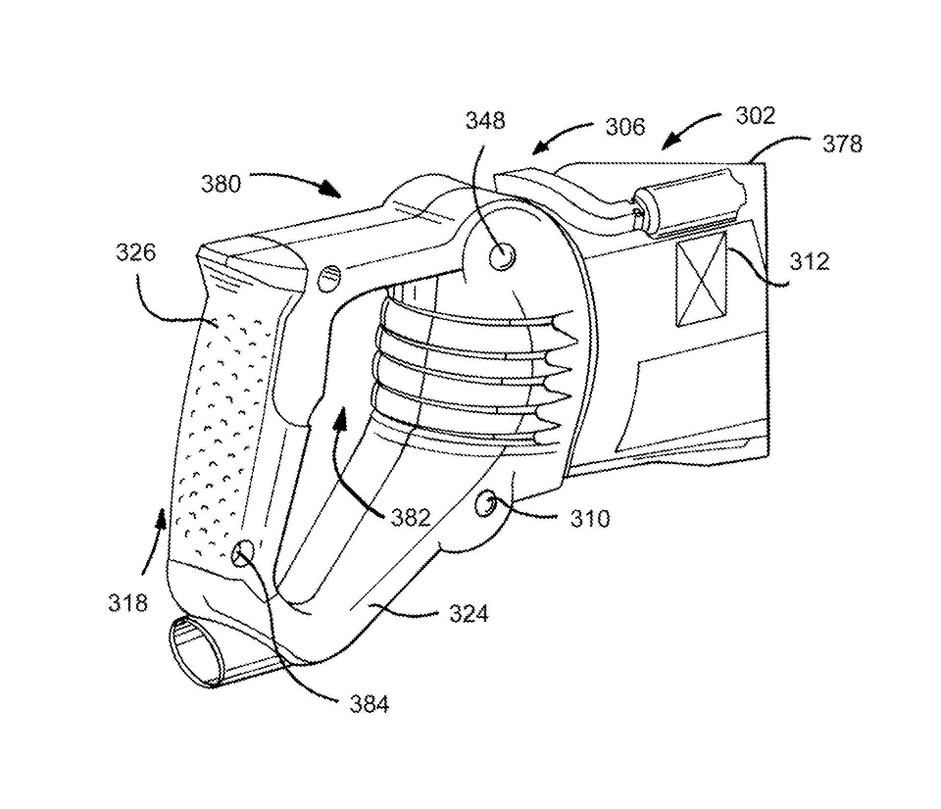
[0009]An embodiment of the invention provides a power tool including a tool body and a handle composed of two halves mounted to the tool body at two upper vibration isolation joints and two lower isolation joints. The four joints provide the means of absorption in isolation of vibrations by allowing the handle to move relative to the tool body while giving the operator lateral stability and torsion control over the tool. The tool body has clearance all the way around the handle to avoid any contact between the handle and the tool body.
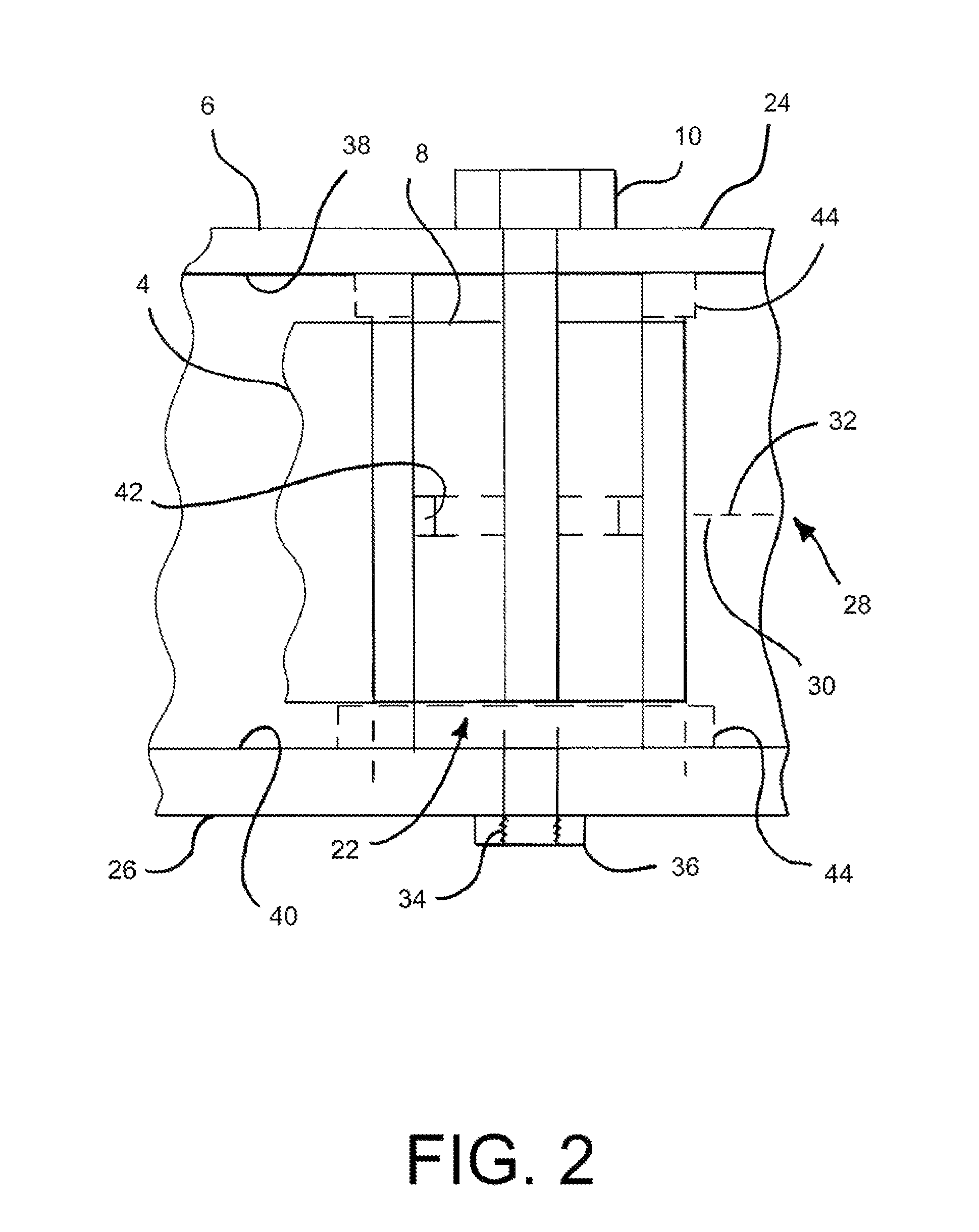
[0054]The technical advantages of the present invention further include the ability to provide a simple cost effective vibration isolator that may comply with government regulations. For example, according to another aspect of the present invention a power tool is provided with a cylindrical dampener element that is captured between the tool body and the housing of the power tool. Thus the present invention provides for a simple cost effective means of isolating vibrations in a power tool.

Problems solved by technology

The motors generate vibrations and frequently some tools, for example cutting tools such as saws, may generate vibrations as well.
The vibrations from the tools and motors of power tools migrate toward the handles and cause fatigue as well as interference with the control of the power tool.
The use of a padded handle may not be effective in reducing the vibration to a sufficient level to minimize fatigue of an operator.

Method used


Image

  • Vibration dampening for a power tool
  • Vibration dampening for a power tool
  • Vibration dampening for a power tool

Examples


Embodiment Construction

[0082]Reference will now be made in detail to various presently preferred embodiments of the invention, examples of which are illustrated in the accompanying drawings. In the various FIGS. some of the structures are referenced with similar reference numerals.

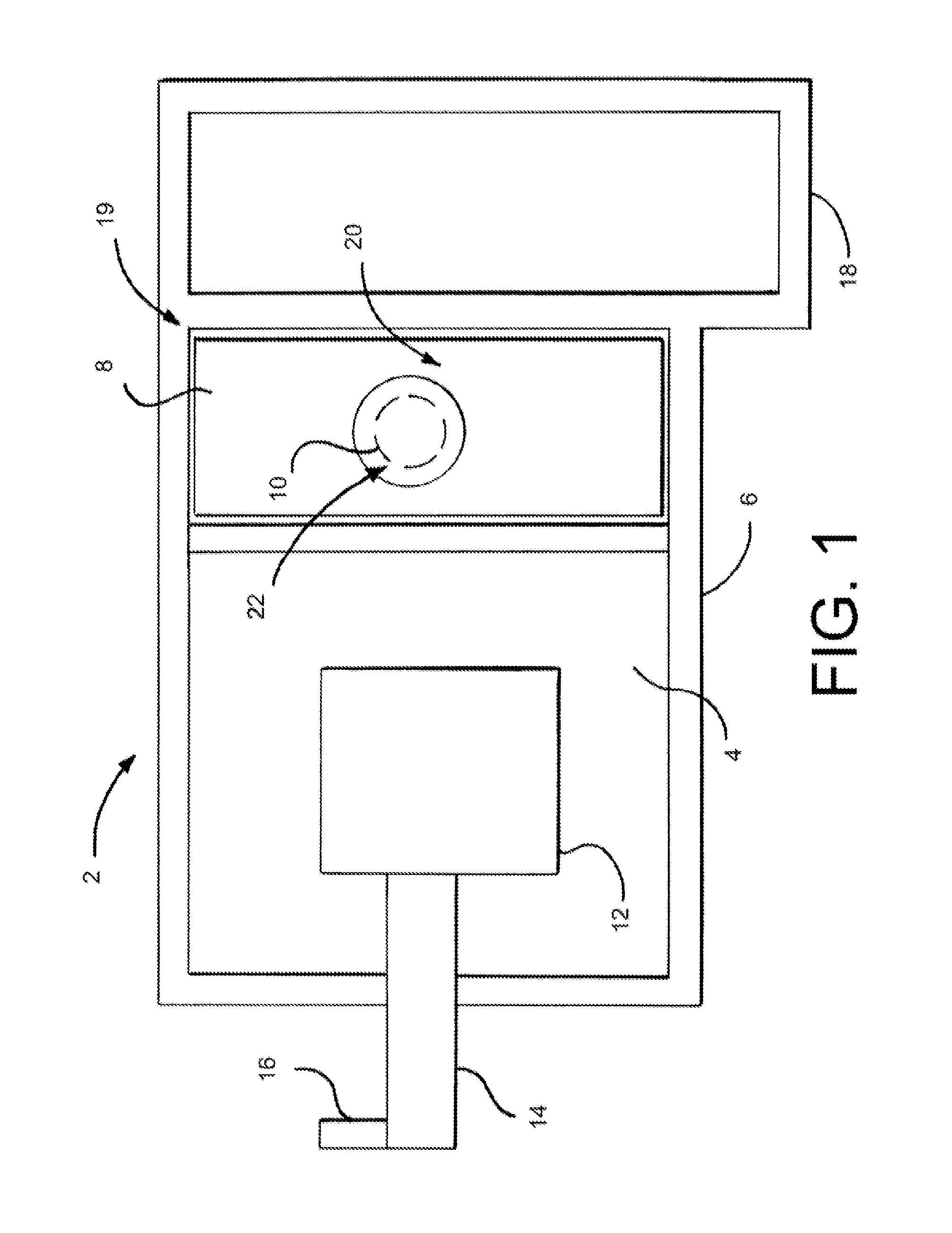
[0083]According to the present invention and referring now to FIG. 1, a power tool 2 is shown. The power tool 2 includes a body 4 and a housing 6 surrounding at least a portion of the body 4. The power tool 2 also includes a first isolator 8 which, as is shown in FIG. 1, is positioned between the body 4 and the housing 6. The first isolator 8 is in contact with the body 4 and the housing 6. The power tool 2 also includes a first fastener 10 connected to the housing 6 to position the first isolator 8 with respect to the housing 6.

[0084]As shown in FIG. 1, the power tool 2 may be any power tool that generates vibration or powers a tool may cause vibration to the power tool 2. The power tool 2 may be driven by for example motor 12....


PUM

PropertyMeasurementUnit
dimensionsaaaaaaaaaa
stiffnessaaaaaaaaaa
cylindrical shapeaaaaaaaaaa

Abstract

A power tool includes a body and a housing surrounding at least a portion of the body. The power tool also includes a first isolator positioned between the body and the housing and in contact with the body and the housing. The power tool also includes a first fastener connected to the housing to position the first isolator with respect to the housing.

Description

[0001]This application is national stage submission under 35 USC 371 based on PCT patent application no. PCT / US2008 / 001536 filed on Feb. 5, 2008, which in turn, is a non provisional of provisional patent application No. 60 / 899,952 filed on Feb. 7, 2007. The disclosures of the two above-identified patent applications are herein incorporated by reference in their entirety.FIELD OF THE INVENTION[0002]The present invention relates to a power tool. More specifically, the present invention relates to a vibration dampener for a power tool.BACKGROUND OF THE INVENTION[0003]Hand-held power tools, for example, power hammers, drills and saws are typically powered by an electric motor. Such powered tools may alternately be powered by pneumatic motors. The motors generate vibrations and frequently some tools, for example cutting tools such as saws, may generate vibrations as well. The vibrations from the tools and motors of power tools migrate toward the handles and cause fatigue as well as inter...

Claims


Application Information

Patent Timeline
Patent Type & Authority Patents(United States)
IPC IPC(8): B25D11/00B25D16/00B23D45/16B25D17/00B25D9/00B25D13/00
CPCB25F5/006B25D2222/57B25D17/043B25D17/24
Inventor MORENO, JAIMEKRONDORFER, HARALDFRANK, HOLGER
Owner ROBERT BOSCH TOOL
Learn More