
Address-sharing system

a technology of address sharing and address sharing, applied in the field of address sharing system, can solve the problems of increasing the cost of processing packet transfer in comparison with routers, preventing bidirectional access from being secured between devices, and introducing napt devices, etc., and achieve the effect of efficient use of port numbers

Inactive Publication Date: 2014-05-06
NEC CORP
View PDF10 Cites 2 Cited by
  • Summary
  • Abstract
  • Description
  • Claims
  • Application Information

AI Technical Summary

Benefits of technology

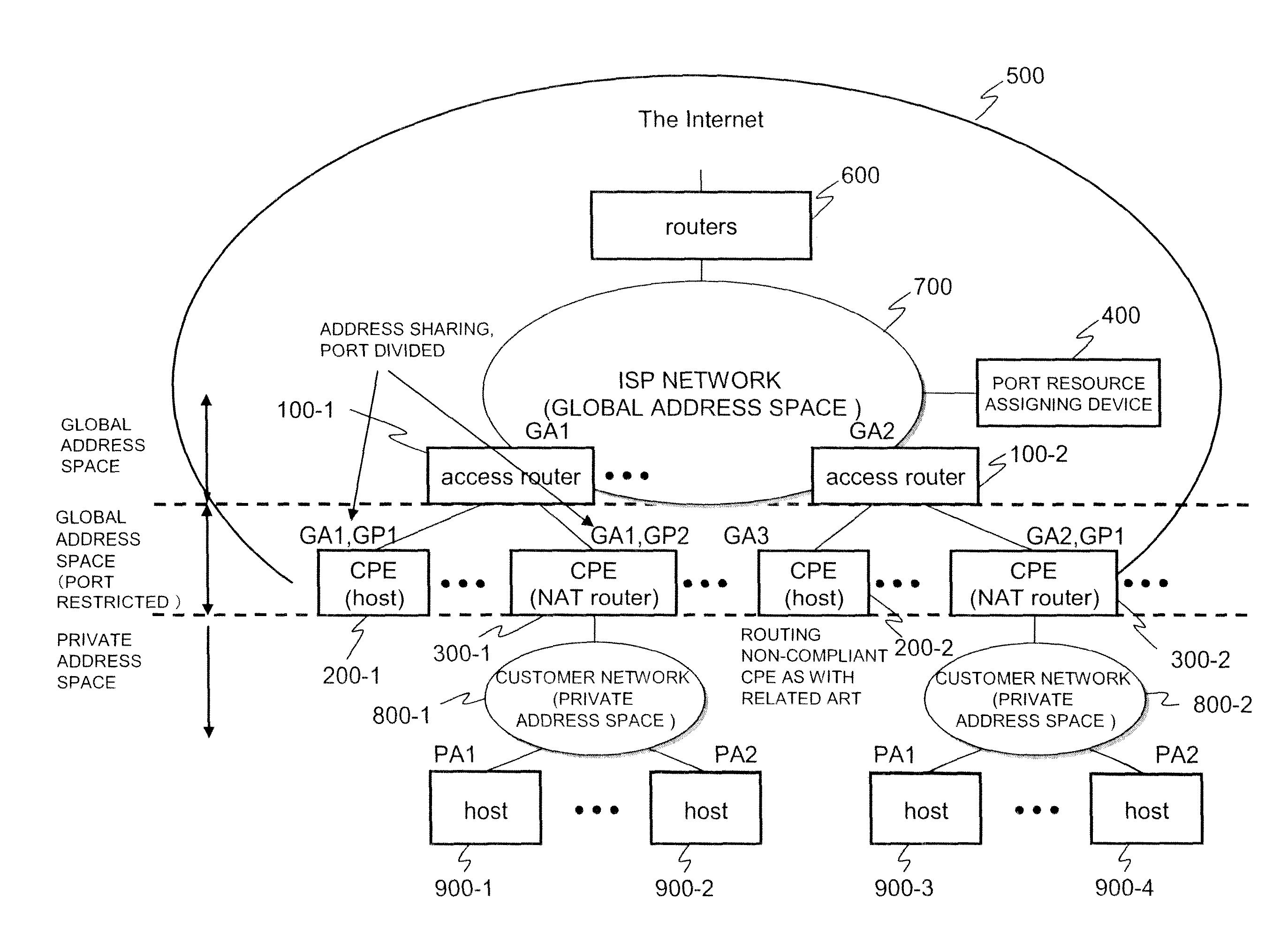
[0057]As described above, the present invention adopts the configuration where connection is established to a global network allowing mutual access using only an IP address and a network other than the global network, an access router performs packet transfer between the networks using an address and a port number, a port resource assigning device manages the port number in a unit of the IP address, and, when performing the packet transfer, assigns the port number managed by means of the IP address preliminarily provided for the access router. The access router performs the packet transfer using the IP address preliminarily provided for the access router and the port number assigned by the port resource assigning device. Accordingly, path control efficiently using the port number can readily be performed.

Problems solved by technology

This generally prevents bidirectional accessibility from being secured between devices with intervention of the NAPT device.
This increases the cost for processing packet transfer in comparison with routers.
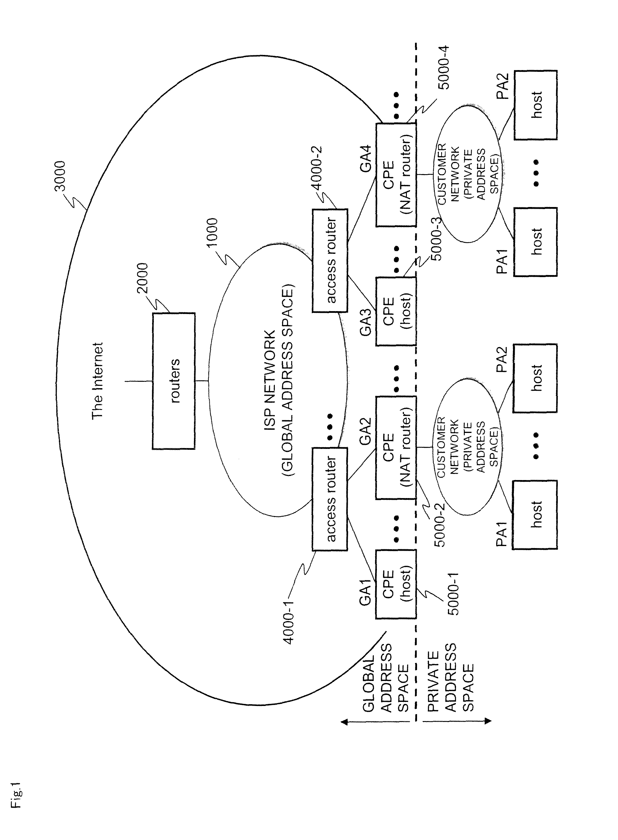
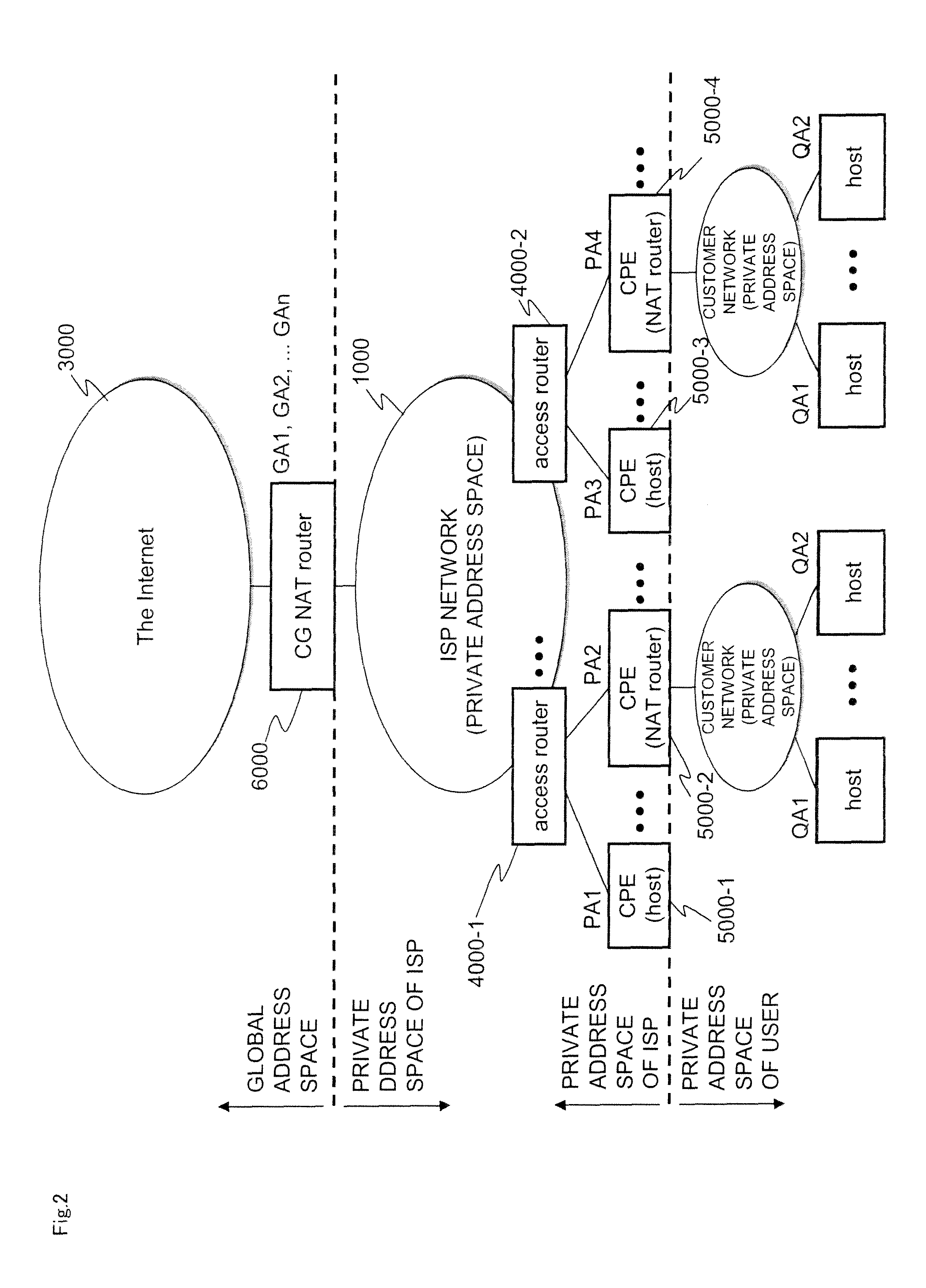
However, an ISP (Internet Service Provider) and the like have not introduced the NAPT devices on a large scale.
(1) It is generally difficult to realize a large NAPT device. One of causes thereof is the difficulty of designing a device having a large address conversion table and maintaining high throughput. Another cause is that, since appearance and disappearance of a connection in a transport layer is based on the appearance and disappearance of a session, an entry is required to be edited each time and thus it is difficult to secure redundancy of the address conversion table. Even if the device can be realized, the above problems cannot completely be solved. Accordingly, it is thought that this becomes a bottleneck of performance and a single point of failure.
(2) In a case where a user of the ISP has already introduced the NAPT device, the address is doubly converted. Accordingly, communication efficiency is reduced. Installation of the NAPT device by the ISP also prevents operation of a protocol (UPnP (Universal Plug and Play) etc.) for allowing access to a device presently on a private network side such as a NAPT device from the Internet side.
(3) The concern is that a private address used in the ISP network may overlap with a private address used by a user in an own network.

Method used


Image

  • Address-sharing system
  • Address-sharing system
  • Address-sharing system

Examples


first exemplary embodiment

[0086]FIG. 5 is a block diagram showing an example of internal configurations of access router 100-1, CPE 200-1 and CPE 300-1 shown in FIG. 4 in a first exemplary embodiment. Access router 100-1 shown in FIG. 4 and access router 100-2 have the same configuration and function; CPE 200-1 and CPE 200-2 have the same configuration and function; CPE 300-1 and CPE 300-2 have the same configuration and function.

[0087]Access router 100-1 shown in FIG. 4 includes routing section 110, port base routing section 120 and unassigned port communication blocker 130, as shown in FIG. 5. Access router 100-1 is connected to port resource assigning device 400.

[0088]Routing section 110 has a routing function as with a typical router.

[0089]Unassigned port communication blocker 130 blocks traffic that uses an inappropriate port number.

[0090]FIG. 6 is a block diagram showing an example of an internal configuration of port base routing section 120 shown in FIG. 5.

[0091]Port base routing section 120 shown in...

second exemplary embodiment

A Case where CPE Uses Assignment Port in Sessions

[0220]In the first exemplary embodiment, the CPE uses one port for one session. However, in a case where the opposite party of communication is different, a single terminal point on the local side may be used for a different connection destination. This configuration allows the port number to be used more efficiently.

[0221]The description will be made on points different from those of the first exemplary embodiment. In a second exemplary embodiment, only the CPE, or NAPT, has a configuration different from that of the first exemplary embodiment.

[0222]FIG. 19 is a block diagram showing an example of an internal configuration of address converter 330-2 in the second exemplary embodiment. Address converter 330-2 is provided in the CPE, or NAPT, as with address converter 330 in the first exemplary embodiment.

[0223]Among configurational elements of address converter 330-2 shown in FIG. 19, the configuration of address conversion table 331-...

example

[0251]The exemplary embodiments of the present invention can be specifically realized using following devices.

[0252]That is any one of pieces of CPE 200-1, 200-2, 300-1 and 300-2, access routers 100-1 and 100-2, port resource assigning device 400 includes a central processing unit (CPU), volatile memory, communication interface, and nonvolatile memory or hard disk. The above operation can be realized by a program stored in the nonvolatile memory or the hard disk, or a program to be loaded after activation using communication interface.

[0253]Each of access routers 100-1 and 100-2 can be realized not only as a single computer but also as a so-called chassis type device, which includes a line card mounted with a communication interface, a CPU card performing control of the entire device and path calculation, a switch fabric module exchanging packets between the cards at high speed, and a service card mounted with another supplementary function. In this case, the routing section, the po...


PUM


Abstract

Access routers (100-1 and 100-2) perform packet transfer using an IP address and a port number between a global network allowing mutual access using the IP address and a network other than the global network. Port resource assigning device (400) manages the port number in units of IP addresses, and, when performing the packet transfer, assigns the port number managed by means of the IP address preliminarily provided for access routers (100-1 and 100-2). Access routers (100-1 and 100-2) perform packet transfer using the IP address preliminarily provided for access router (100-1 and 100-2) and the port number assigned by port resource assigning device (400).

Description

[0001]The present application is a Continuation Application of International Application No. PCT / JP2010 / 053971 filed on Mar. 10, 2010, which claims priority to Japanese Patent Application No. 2009-099853, filed on Apr. 16, 2009, both of which are incorporated herein in their entirety.TECHNICAL FIELD[0002]The present invention relates to an address-sharing system that shares an address, an access router, a port resource assigning device, a connection device, an address-sharing method, and a program.BACKGROUND ART[0003]In general, a packet transfer device, such as a router, in an IP (Internet Protocol) network has a mechanism that identifies a host node by means of the destination IP address of a packet, selects a packet distribution path according to the IP address and thus provides accessibility.[0004]It is expected that addresses for IP version 4 (IPv4) will be exhausted in the near future. After exhaustion of addresses for IP version 4, no IPv4 address can be newly acquired. Thus,...

Claims


Application Information

Patent Timeline
Patent Type & Authority Patents(United States)
IPC IPC(8): G01R31/08
CPCH04L61/2514H04L61/2015H04L61/2592H04L29/12377H04L12/6418H04L12/4633H04L61/2517H04L29/12367H04L12/66H04L61/5014
Inventor KARINO, SHUICHI
Owner NEC CORP
Learn More