Piezoelectric micro-blower

a micro-blower and piezoelectric technology, applied in the direction of positive displacement liquid engines, piezoelectric/electrostrictive/magnetostrictive devices, electrical apparatus, etc., can solve the problems of diffused airflow and inability to achieve desired flow ra

Active Publication Date: 2014-05-13
MURATA MFG CO LTD
View PDF10 Cites 11 Cited by
  • Summary
  • Abstract
  • Description
  • Claims
  • Application Information

AI Technical Summary

Benefits of technology

[0044]The advantageous effects provided by each of the first opening 12 and the second opening 52 preferably including nine holes each (see FIG. 2) will be described below in contrast to comparative examples 1 and 2. FIG. 5A shows the comparative example 1 in which each of the first opening 12 and the second opening 52 in the piezoelectric micro-blower A of the first preferred embodiment is composed of a single hole similarly to International Publication No. WO2008 / 69266. FIG. 5B shows the comparative example 2 in which the first opening 12 is composed of a plurality of holes and the second opening 52 is composed of a single hole. When the first opening 12 has a multi-hole structure and the second opening 52 is composed of a single hole as in the comparative example 2, the second opening 52 is sized to be able to include the entire first opening 12. Here, each dimension is as follows. The cross-sectional area in the case where the first opening is composed of a single hole and the total cross-sectional area in the case where the first opening is composed of a plurality of holes are set so as to be the same.
provided by each of the first opening 12 and the second opening 52 preferably including nine holes each (see FIG. 2) will be described below in contrast to comparative examples 1 and 2. FIG. 5A shows the comparative

Problems solved by technology

However, the space around the holes 115 in the second membrane 114 is an opened space, and thus the discharged airflow diffuses and a desired flow rate cannot be obtained.

Method used


Image

  • Piezoelectric micro-blower
  • Piezoelectric micro-blower
  • Piezoelectric micro-blower

Examples


first preferred embodiment

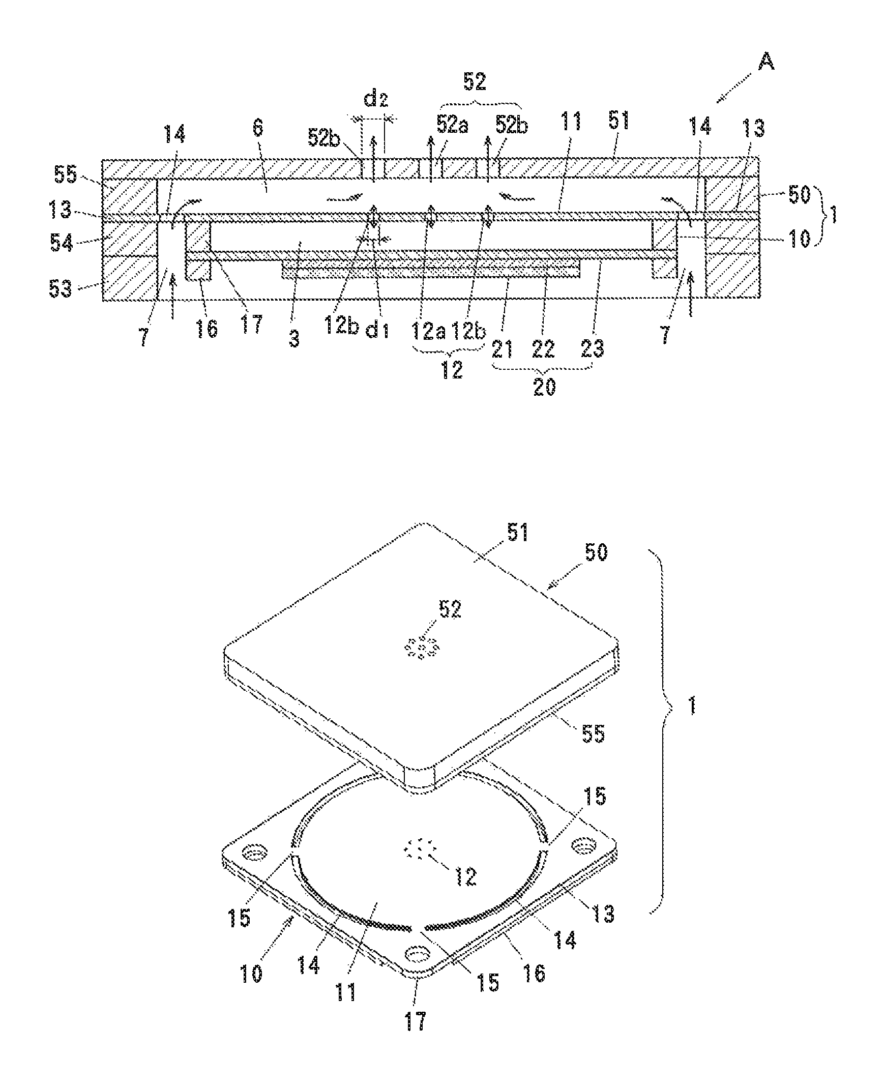
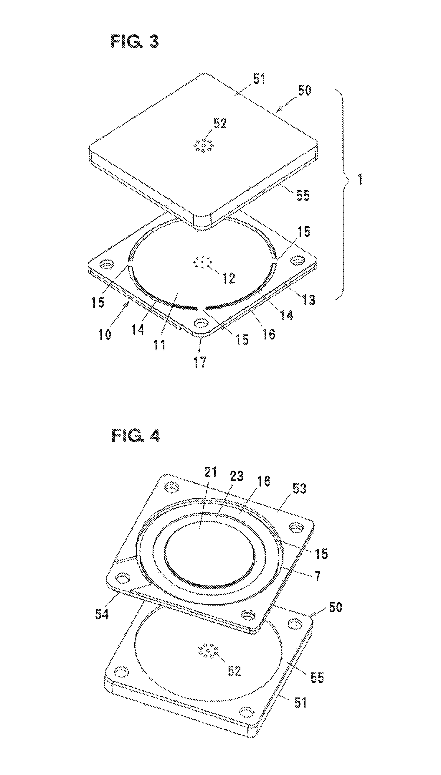
[0046]Piezoelectric substance 21: PZT having a thickness of 0.15 mm and a diameter of φ 11 mm.

[0047]Intermediate plate 22: SUS430 having a thickness of 0.2 mm and a diameter of φ 11 mm.

[0048]Diaphragm 23: 42Ni having a thickness of 0.05 mm and a diameter of φ 17 mm.

[0049]Top plate 11: SUS430 having a thickness of 0.1 mm.

[0050]Blower chamber 3: SUS430 having a thickness of 0.15 mm and a diameter of φ14 mm.

[0051]Spring connection portions 15: a length of 0.5 mm and a width of 1 mm.

[0052]Inlet 7: a width of 0.5 mm.

[0053]Outer case 50: a thickness of 3.0 mm, 20 mm×20 mm.

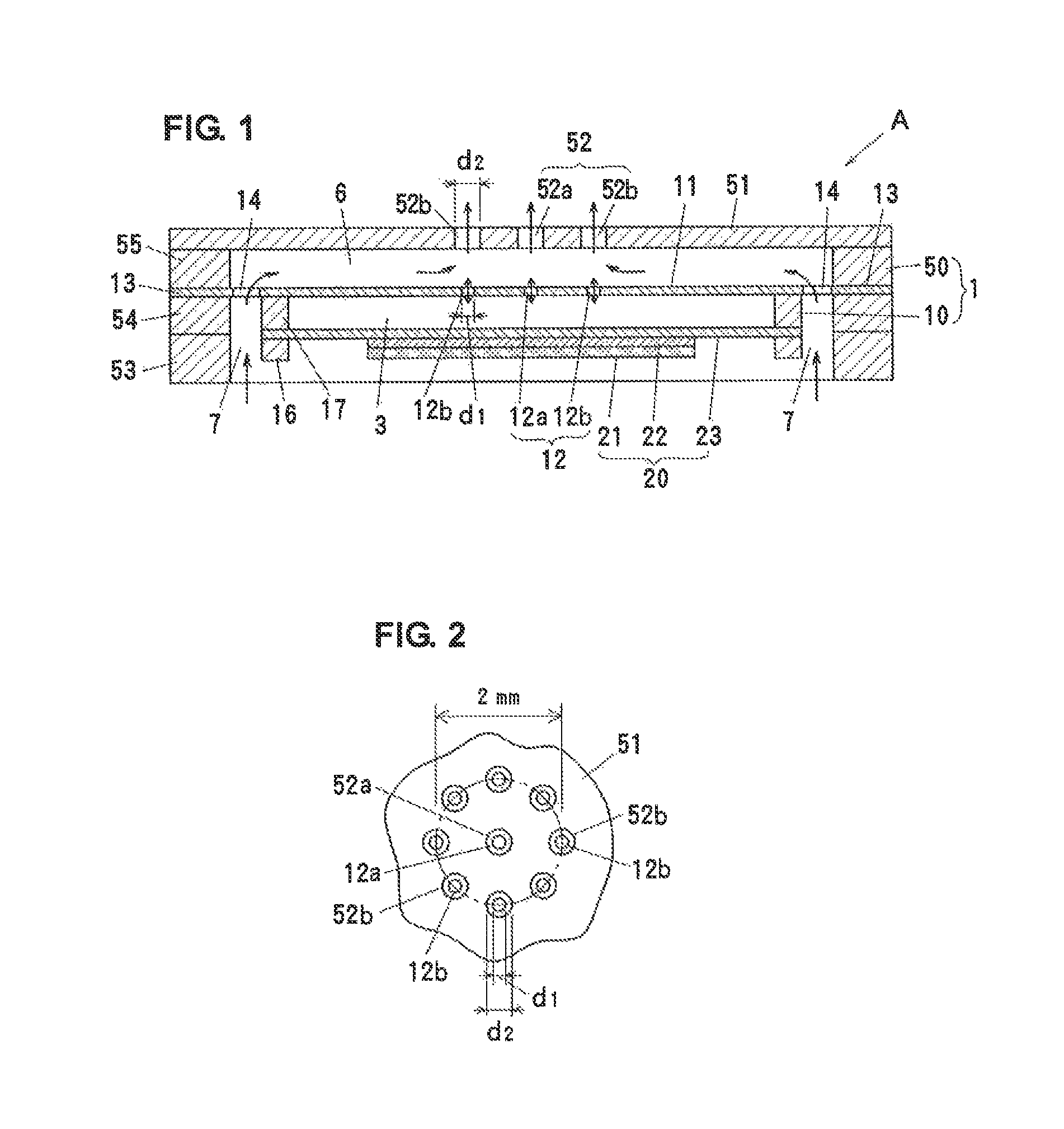
[0054]First opening 12: φ 0.2 mm×nine holes, hole distribution diameter=φ 2 mm.

[0055]Second opening 52: φ 0.4 mm×nine holes.

[0056]Driving voltage: 15 Vp-p

[0057]Driving frequency: 25 kHz (vibrating plate 20 and top plate 11 resonate in third-order resonance)

second preferred embodiment

[0075]FIG. 9 shows a second preferred embodiment of the piezoelectric micro-blower according to the present invention. In the micro-blower B, a cylindrical nozzle 56 is arranged on the top plate (second wall portion) 51 so as to surround the entirety of the second opening 52. In a preferred embodiment of the present invention, as shown in FIG. 13B, the flow speed of air discharged from each hole of the second opening 52 is low as compared to the flow speed of air discharged from a single hole. Air discharged from the holes 52b arranged in the outer peripheral portion may peripherally diffuse. Thus, by arranging the nozzle 56 on the top surface of the top plate 51 so as to surround the holes 52b arranged in the outer peripheral portion, flows of air discharged from the holes 52a and 52b are converged into one flow and diffusion of air flow can be prevented and suppressed. It should be noted that the shape of the nozzle 56 is not limited to a simple cylindrical shape and can be a tape...

third preferred embodiment

[0076]FIGS. 10A and 10B show a third preferred embodiment of the first opening 12 and the second opening 52. In this preferred embodiment, each of the first opening 12 and the second opening 52 preferably includes 37 small holes arranged in a hexagon, for example. Preferably, the diameter of each hole of the first opening 12 is φ about 0.1 mm, and the interval p1 is about 0.4 mm, for example. Similarly, preferably, the diameter of each hole of the second opening 52 is φ about 0.3 mm, and the interval p2 is about 0.4 mm, for example. The central axis of each hole of the first opening 12 and the central axis of each hole of the second opening 52 are aligned in a straight line. The other structure preferably is the same or substantially the same as that in the first preferably embodiment.

[0077]The advantageous effects achieved by each of the first opening 12 and the second opening 52 including 37 holes will be described in contrast to a comparative example 1. The comparative example 1 ...


PUM


Abstract

A piezoelectric micro-blower includes a blower chamber located between a blower body and a vibrating plate, a first wall portion of the blower body arranged to face the vibrating plate across the blower chamber so as to vibrate with vibrations of the vibrating plate, a first opening in the first wall portion, a second wall portion on the opposite side of the first wall portion with respect to the blower chamber, a second opening in a portion of the second wall portion which faces the first opening, and an inflow passage located between the first wall portion and the second wall portion. Each of the first and second openings includes a plurality of holes, and each hole of the first opening and each hole of the second opening are arranged to face each other. Thus, noise is significantly reduced while the flow characteristic is maintained.

Description

BACKGROUND OF THE INVENTION[0001]1. Field of the Invention[0002]The present invention relates to a piezoelectric micro-blower suitable for conveying compressible fluid such as air and gas.[0003]2. Description of the Related Art[0004]A piezoelectric micro-blower is known as an air blower for dissipating heat generated in a housing of a portable electronic apparatus or for supplying oxygen required to generate electric power in a fuel cell. The piezoelectric micro-blower is a type of pump which includes a diaphragm which bends when a voltage is applied to a piezoelectric element, and is advantageous in that the piezoelectric micro-blower can be configured to have a simple structure, small size and thickness, and low power consumption.[0005]Japanese Unexamined Patent Application Publication No. 64-2793 (FIG. 14) discloses a flow generating apparatus including a piezoelectric element. In the flow generating apparatus, as shown in FIG. 14, a compression chamber 103 is formed between a ba...

Claims


Application Information

Patent Timeline
Patent Type & Authority Patents(United States)
IPC IPC(8): F04B17/00H01L41/047
CPCF04B43/095F04B43/046
Inventor FUJISAKI, MASAAKIHIRATA, ATSUHIKOKURIHARA, KIYOSHI
Owner MURATA MFG CO LTD
Why Eureka
Try Eureka