Excited frame vibratory conveyor

a vibratory conveyor and excited frame technology, applied in conveyors, conveyors, jigging conveyors, etc., can solve the problems of increasing the cost of fabricating vibratory conveyors, energized motors actually amplifying lateral motion in an adverse manner, and limiting the use of conveyors with relatively short bed lengths, so as to reduce the movement of the base frame

Active Publication Date: 2014-05-27
KII TEKU INC
View PDF19 Cites 16 Cited by
  • Summary
  • Abstract
  • Description
  • Claims
  • Application Information

AI Technical Summary

Benefits of technology

[0008]A first aspect of the present invention relates to an excited frame vibratory conveyor which includes a base frame having a longitudinal, transverse and vertical axes; a motor mount made integral with the base frame, and which has a top and bottom facing surface; a first and second vibratory motor which are individually mounted on the top and bottom facing surfaces of the motor mount; and an electrical circuit for energizing and de-energizing the respective vibratory motors so as to substantially reduce movement of the base frame along the vertical axis, and which is caused, at least in part, by the non-synchronous operation of the first and second vibratory motors.
[0009]Still another aspect of the present invention relates to an excited frame vibratory conveyor which includes a base frame having spaced, sidewalls; a plurality of elongated, planar biasing springs mounted on, and extending upwardly relative to, the respective sidewalls of the base frame; a vibratory conveyor bed mounted on the respective plurality of the elongated, planar biasing springs, and which is located in predetermined, spaced relation relative to the spaced sidewalls; a motor mount made integral with, and extending therebetween the respective sidewalls of the base frame, and wherein the motor mount has opposite end portions which are substantially vertically oriented, and an intermediate portion which is made integral with the opposite end portions of the motor mount, and which is acutely, angularly oriented relative thereto, and wherein the intermediate portion has an upwardly and a downwardly facing surface; first and second vibratory motors which are selectively energizable, and which individually mount a rotatable eccentric weight which have substantially similar masses, and wherein the respective first and second vibratory motors are individually mounted on the upwardly and downwardly facing surfaces of the motor mount; and an electrical circuit for selectively energizing and deenergizing the respective first and second vibratory motors so as to facilitate the synchronization of the respective vibratory motors, and which further substantially reduces any vertical movement of the base frame which is caused, at least in part, by the non-synchronous rotation of the respective eccentric weights which occurs upon the energizing or deenergizing of the respective first and second vibratory motors.

Problems solved by technology

While these earlier designed excited frame conveyors have operated with a great deal of success, shortcomings have been attendant to their individual designs, and which have limited their use to conveyors having relatively short bed lengths.
As described in this patent, a failure to minimize this lateral motion could result in the energized motors actually amplifying the lateral motion in an adverse manner, if the starting sequence is not followed.
Common among the deficiencies as seen in the prior art practices is that manufacturers must fabricate or provide relatively stiff or heavy base frames in order to prevent lateral, sideways motion of the frames, and conveyor beds, during operation of these devices.
This requirement to provide a relatively stiff base frame comes with a price, that being, as the excited frame vibratory conveyor gets longer, the cost of fabricating the vibratory conveyor gets increasingly more expensive.
While some of these efforts have been somewhat successful, problems remain relative to fabricating cost-effective, excited frame vibratory conveyors having increased lengths and reliability.
Additionally, experience in the field has demonstrated that as the vibratory motors have increased in horsepower, detrimental, vertical motion is sometimes imparted to the base frames upon the energizing of the respective motors.
As might be expected, and understood by those skilled in the art, this vertical motion of the base frame is not advantageous, especially when such vibratory conveyor devices are located on overhead second, or mezzanine production or factory floors.

Method used


Image

  • Excited frame vibratory conveyor
  • Excited frame vibratory conveyor
  • Excited frame vibratory conveyor

Examples


Embodiment Construction

[0019]This disclosure of the invention is submitted in furtherance of the constitutional purposes of the U.S. Patent laws “to promote the progress of science and useful arts.” (Article I, Section 8).

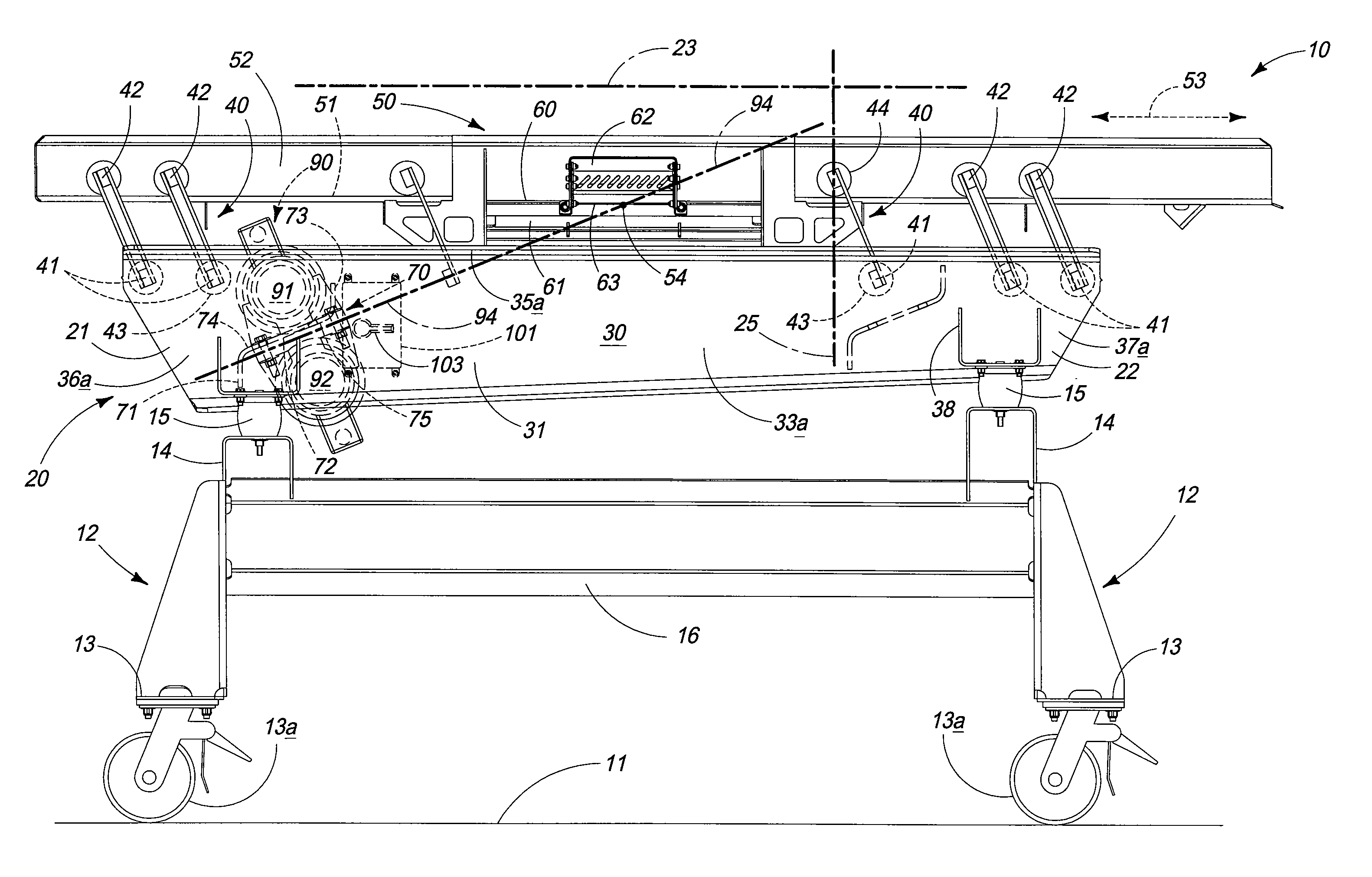
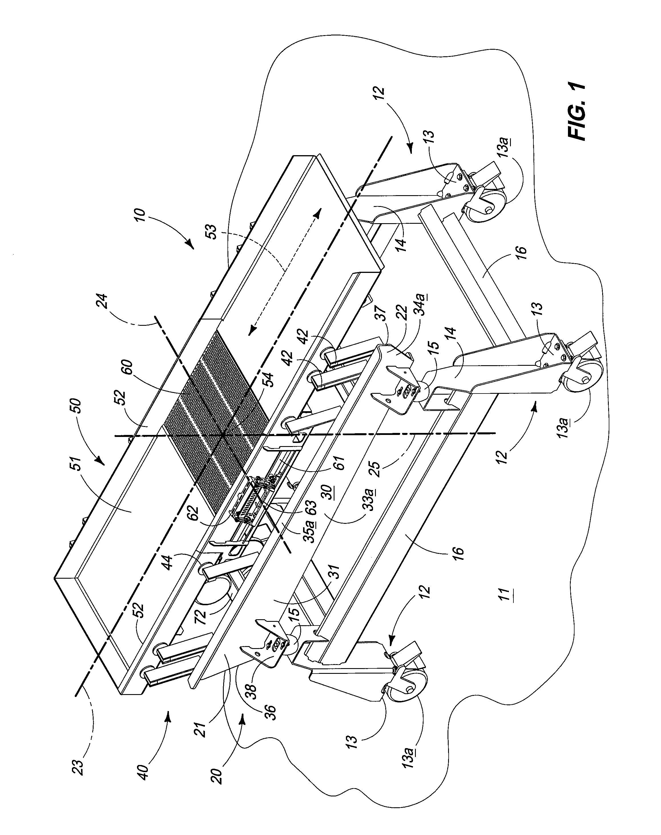
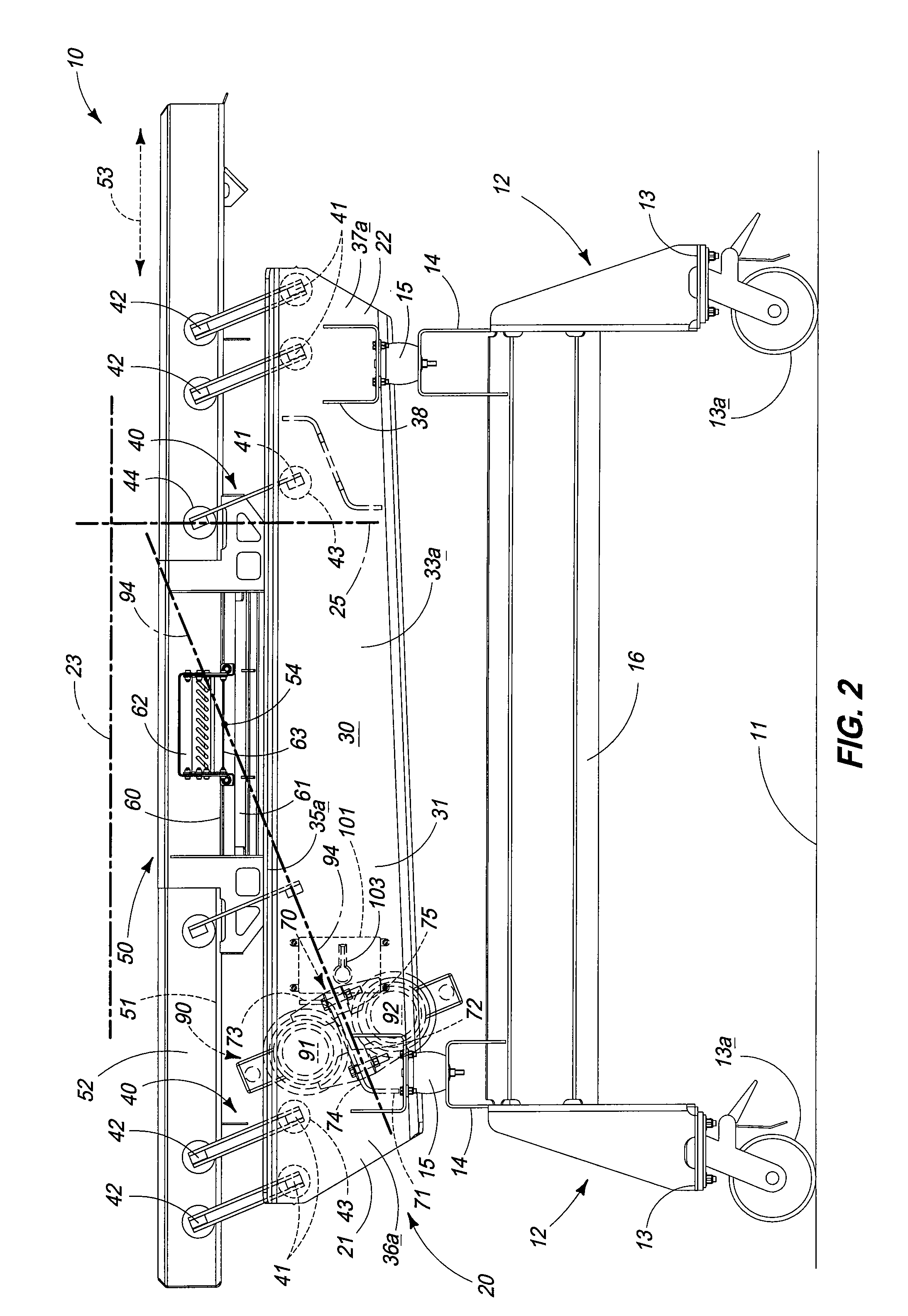
[0020]The excited frame vibratory conveyor of the present invention is generally indicated by the numeral 10 in FIG. 1 and following. In this regard, the present invention 10 as shown in the drawings [FIG. 2] is positioned or otherwise supported on the surface of the earth or an underlying supporting floor which is generally indicated by the numeral 11. The present invention 10 further includes a multiplicity of supporting legs, here indicated by the numeral 12, and which supports the invention in spaced relation relative to the surface of the earth 11. The multiplicity of supporting legs 12, have a first end 13, which is positioned near the supporting surface 11. The first end 13 has affixed thereon individual casters 13A which allows the present invention 10 to be easily moved along th...


PUM


Abstract

An excited frame vibratory conveyor is described and which includes a base frame; a motor mount made integral and with the base frame; a pair of vibratory motors mounted on the motor mount; and an electrical circuit for energizing the pair of vibratory motors in a fashion which reduces movement of the base frame in a vertical direction.

Description

TECHNICAL FIELD[0001]The present invention relates to an excited frame vibratory conveyor, and more specifically, to a device which includes a novel motor mount which is made integral with a base frame, and which further mounts a pair of vibratory motors, and which are operable to impart reciprocal vibratory motion to a conveyor bed. The invention further includes an electrical circuit, which facilitates the synchronous operation of the vibratory motors employed with the present invention.BACKGROUND OF THE INVENTION[0002]Excited frame vibratory conveyors are known in the art. For example, the Office's attention is directed to U.S. Pat. No. 4,313,535, which is incorporated by reference herein, and which describes an exemplary excited frame conveying apparatus that has performed extremely well in the past, and which is useful for transporting bulk products over relatively short distances. While these earlier designed excited frame conveyors have operated with a great deal of success, ...

Claims


Application Information

Patent Timeline
Patent Type & Authority Patents(United States)
IPC IPC(8): B65G27/20
CPCB65G27/24B65G27/28
Inventor WOILER, CHRISDUNHAM, DEANSCHMIDTGALL, MARKBRANT, JEFFRICKARD, TIMJAMESON, CHUCK
Owner KII TEKU INC
Why Eureka
Try Eureka