End effector identification by mechanical features

a technology of end effectors and mechanical features, applied in the field of surgical instruments, can solve the problems of fatigued hands of surgeons, limited user control of the stapling process of powered devices,

Inactive Publication Date: 2014-05-27
TYCO HEALTHCARE GRP LP
View PDF94 Cites 1183 Cited by
  • Summary
  • Abstract
  • Description
  • Claims
  • Application Information

AI Technical Summary

Problems solved by technology

Current known devices can typically require 10-60 pounds of manual hand force to clamp tissue and deploy and form surgical fasteners in tissue which, over repeated use, can cause a surgeon's hand to become fatigued.
However, these motor powered devices only provide for limited user control of the stapling process.

Method used


Image

  • End effector identification by mechanical features
  • End effector identification by mechanical features
  • End effector identification by mechanical features

Examples


Embodiment Construction

[0022]Embodiments of the presently disclosed powered surgical instrument are now described in detail with reference to the drawings, in which like reference numerals designate identical or corresponding elements in each of the several views. As used herein the term “distal” refers to that portion of the powered surgical instrument, or component thereof, farther from the user while the term “proximal” refers to that portion of the powered surgical instrument or component thereof, closer to the user.

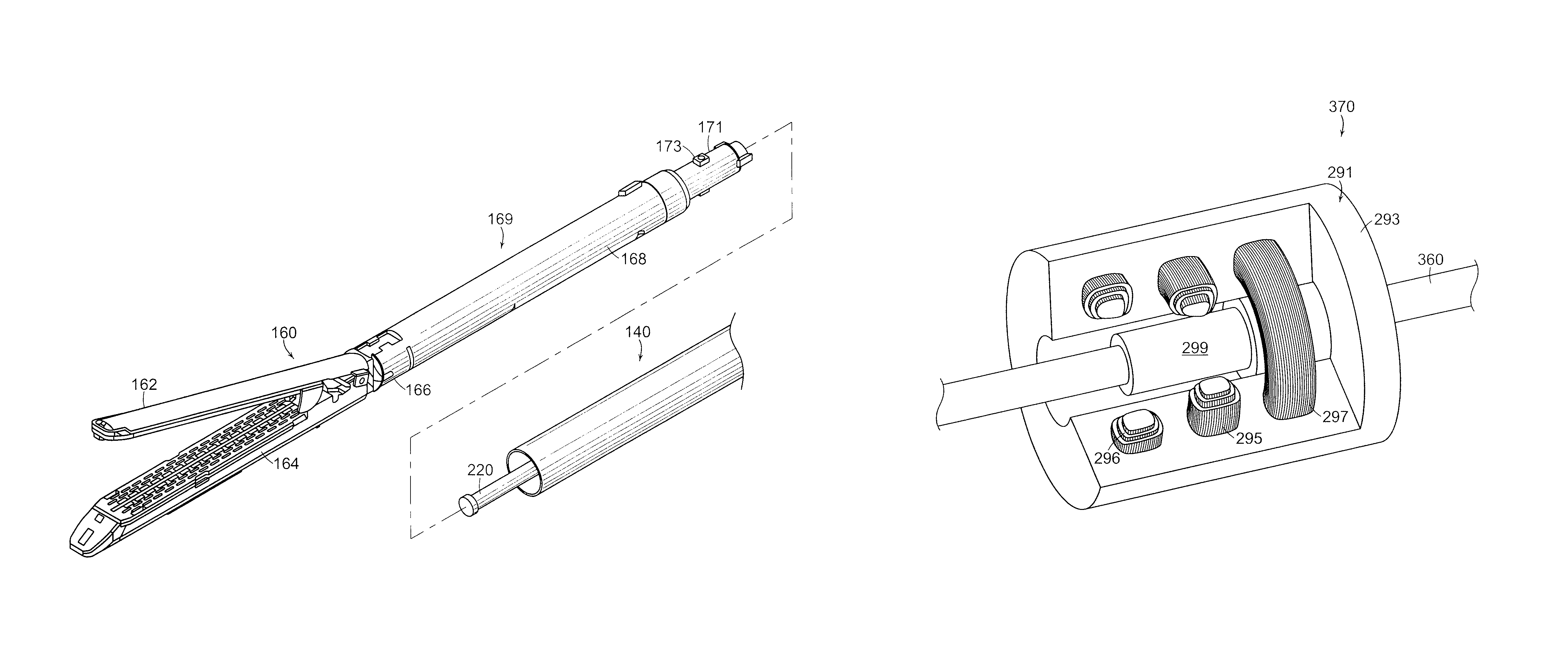
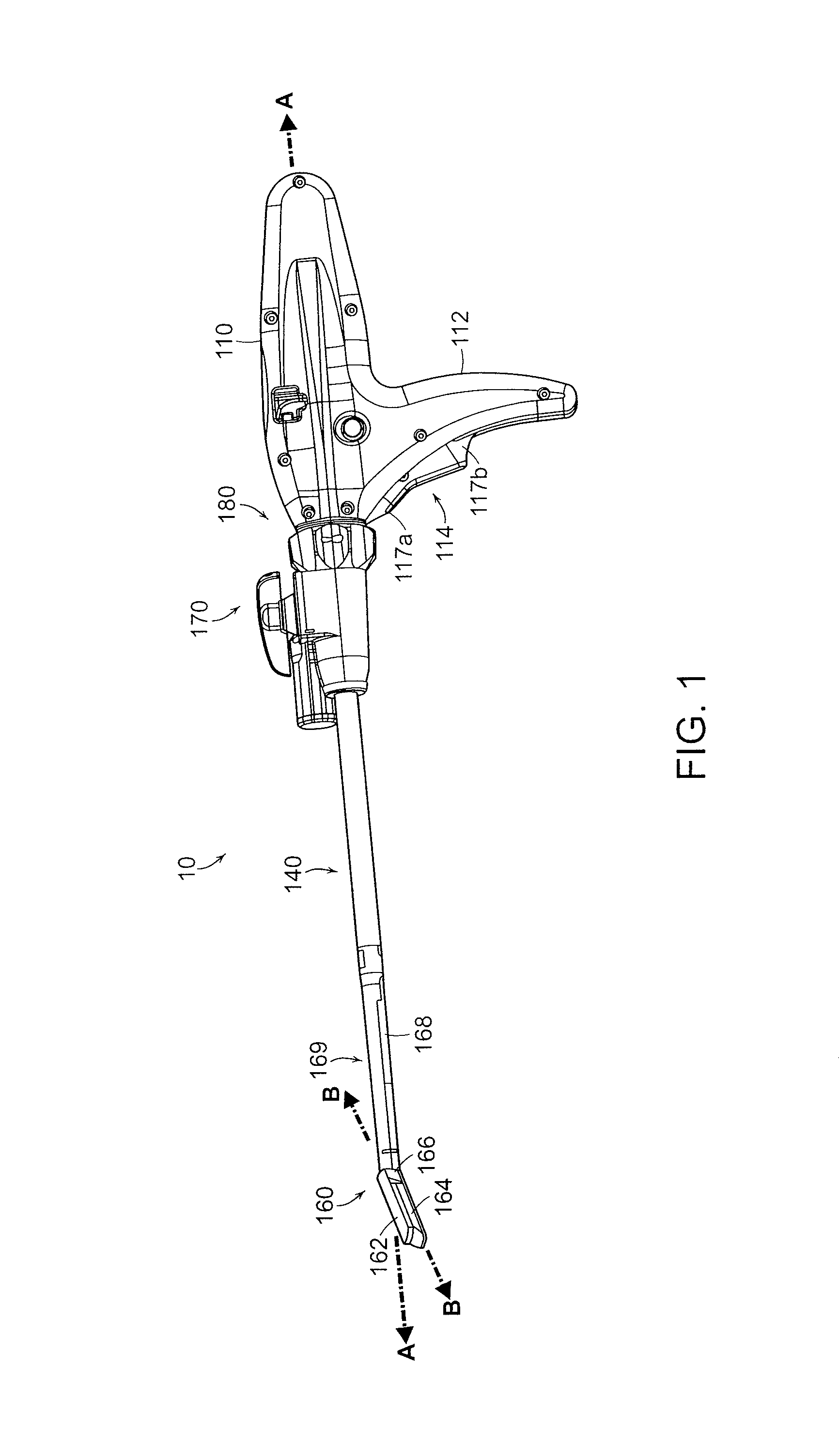
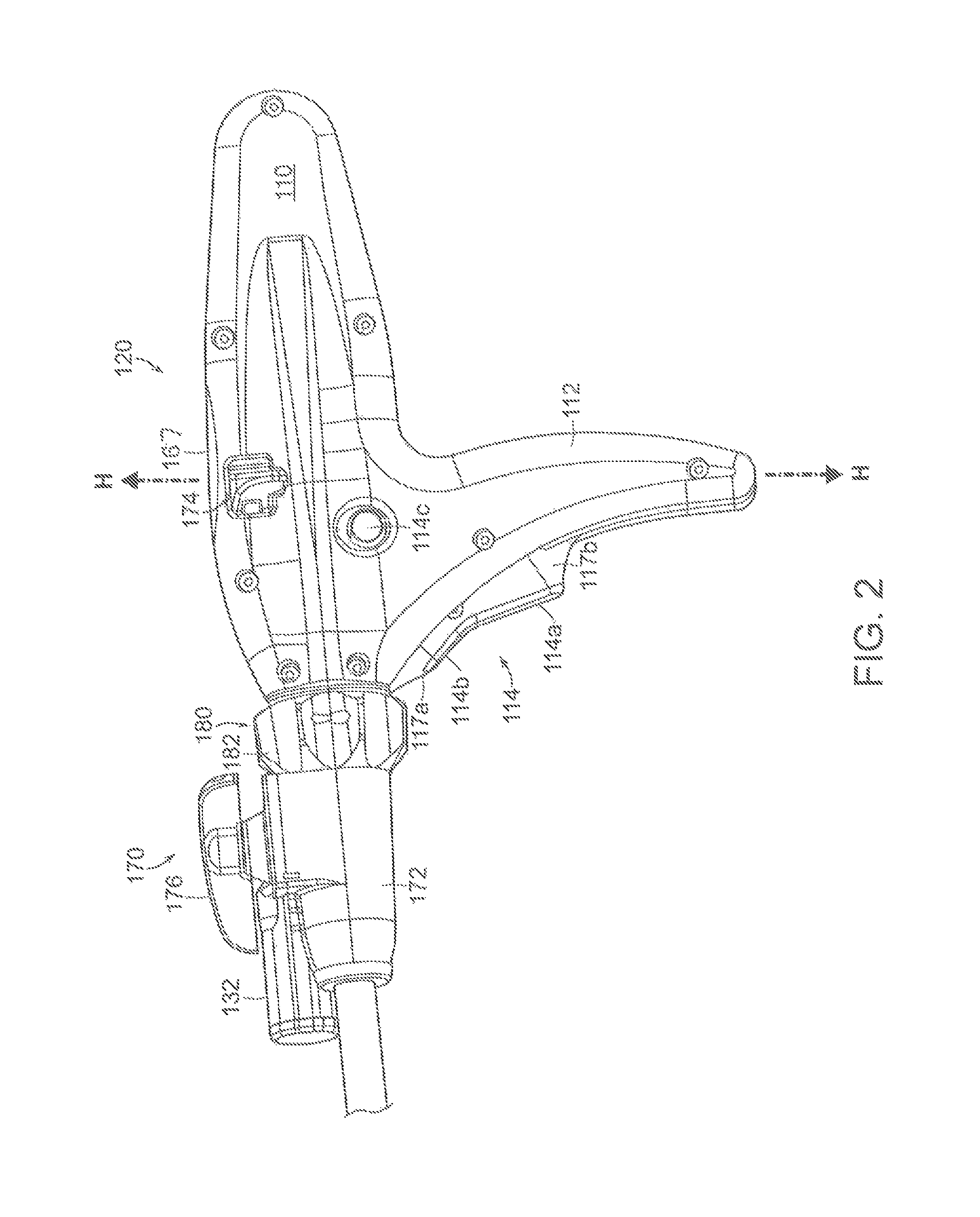
[0023]A powered surgical instrument, e.g., a surgical stapler, in accordance with the present disclosure is referred to in the figures as reference numeral 10. Referring initially to FIG. 1, powered surgical instrument 10 includes a housing 110, a body portion, such as, for example, an endoscopic portion 140 defining a first longitudinal axis A-A extending therethrough, and a loading unit 169. Loading unit 169 includes a proximal body portion 168 and an articulating tool assembly (e.g., en...


PUM

PropertyMeasurementUnit
distanceaaaaaaaaaa
angleaaaaaaaaaa
firing stroke lengthaaaaaaaaaa

Abstract

According to one aspect of the present disclosure, a surgical instrument is disclosed. The instrument includes a handle portion, a body portion extending distally from the handle portion and defining a first longitudinal axis and a loading unit. The loading unit includes a tool assembly, the loading adapted to be coupled to the body portion. The instrument also includes a sensor tube movably positioned within the body portion, the sensor tube adapted to engage the loading unit and a load switch coupled to a microcontroller. The load switch is adapted to be actuated by the sensor tube when the sensor tube is engaged by the loading unit being inserted into the body portion.

Description

CROSS-REFERENCE TO RELATED APPLICATION[0001]The present application claims the benefit of and priority to U.S. Provisional Application Ser. No. 61 / 225,377 filed on Jul. 14, 2009 and is a continuation in part application of U.S. application Ser. No. 12 / 345,167 filed on Dec. 28, 2008, which is a continuation application of U.S. application Ser. No. 11 / 544,203 filed on Oct. 6, 2006, issued as U.S. Pat. No. 7,481,348, and of U.S. application Ser. No. 12 / 189,834 filed on Aug. 12, 2008, which claims priority to a U.S. Provisional Application Ser. No. 60 / 997,854 filed on Oct. 5, 2007, the entire contents of all of which are hereby incorporated by reference herein.BACKGROUND[0002]1. Technical Field[0003]The present disclosure relates to a surgical instrument adapted to be coupled to removable loading units having various end effectors. More particularly, the present disclosure relates to a surgical instrument which includes a mechanism for identifying the type of an end effector mounted to ...

Claims


Application Information

Patent Timeline
Patent Type & Authority Patents(United States)
IPC IPC(8): A61B17/10A61B17/04
CPCA61B2017/00734A61B2017/00017A61B2017/00725A61B17/07207A61B2017/00482A61B17/068A61B2019/448A61B2017/00473A61B2017/00398A61B2017/2927A61B2017/320052A61B17/105A61B17/072A61B2017/0046A61B2562/00A61B17/00234A61B90/98A61B2090/0808
Inventor ROSS, ADAMZEMLOK, MICHAELMARCZYK, STANISLAW
Owner TYCO HEALTHCARE GRP LP
Why Eureka
Try Eureka