
Locking threaded fastener

a threaded fastener and locking technology, applied in the direction of threaded fasteners, fastening means, screws, etc., can solve the problems of relatively low installation torque, unsuitability of the lock nut for its intended application, and loosening of the element's grip, so as to improve the balance of simplicity, cost, and performance. , the effect of improving the structure and function

Inactive Publication Date: 2014-05-27
FLOW RITE CONTROLS
View PDF51 Cites 4 Cited by
  • Summary
  • Abstract
  • Description
  • Claims
  • Application Information

AI Technical Summary

Benefits of technology

The disclosed lock nut has improved structure and function over previous lock nuts. It maintains the simplicity of previous lock nuts while improving performance. The new lock nut has a nut body, a locking element, and a retainer. The locking element is surrounded by the nut body and partially covered by the retainer. The locking element and recesses are dimensioned so that the second tang comes into contact with a wall of the second recess when a predetermined amount of removal torque is applied to the lock nut. This contact limits the amount of tension applied to the locking element, so that the removal torque can be controlled and the locking element is not damaged. The locking element also includes a coil portion and two tangs extending from the coil portion. The locking element is fixed with respect to the nut body to prevent angular movement of the first tang with respect to the body. The retainer at least partially axially covers the locking element to protect it from dirt, grease, and other contaminants. The retainer cover may have a seal against the threaded member and may be elastic to enhance the seal.

Problems solved by technology

The opposite force, compression, is created on the locking element during tightening (i.e. installation), which causes the locking element to loosen its grip so that there is relatively low installation torque.
Unfortunately, the through slots of the noted lock nuts permit dirt, grease, and other contaminants to enter the lock nut through the slot.
Such a change can make the lock nut unsuited for its intended application.

Method used


Image

  • Locking threaded fastener
  • Locking threaded fastener
  • Locking threaded fastener

Examples


first embodiment

I. First Embodiment

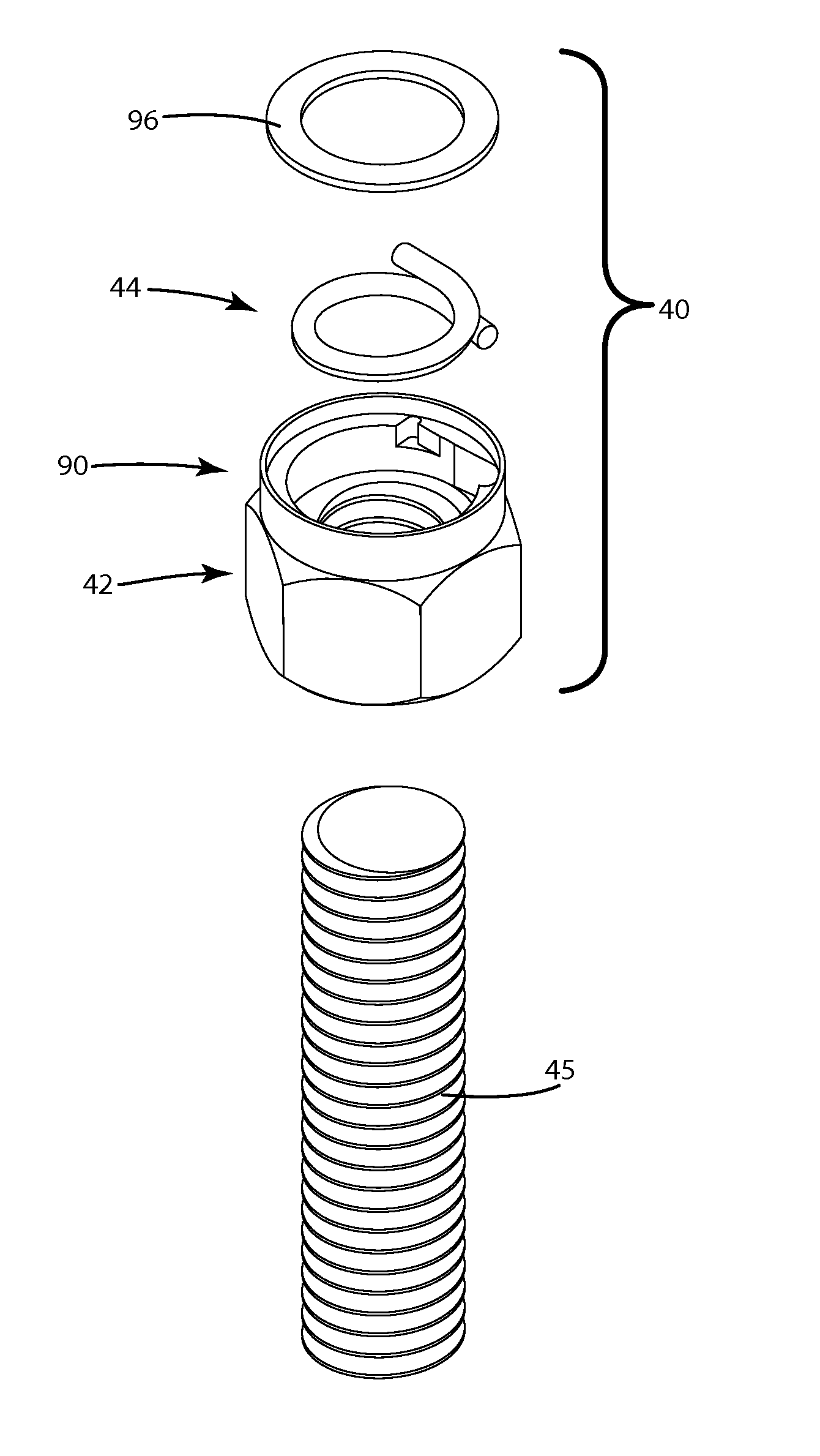
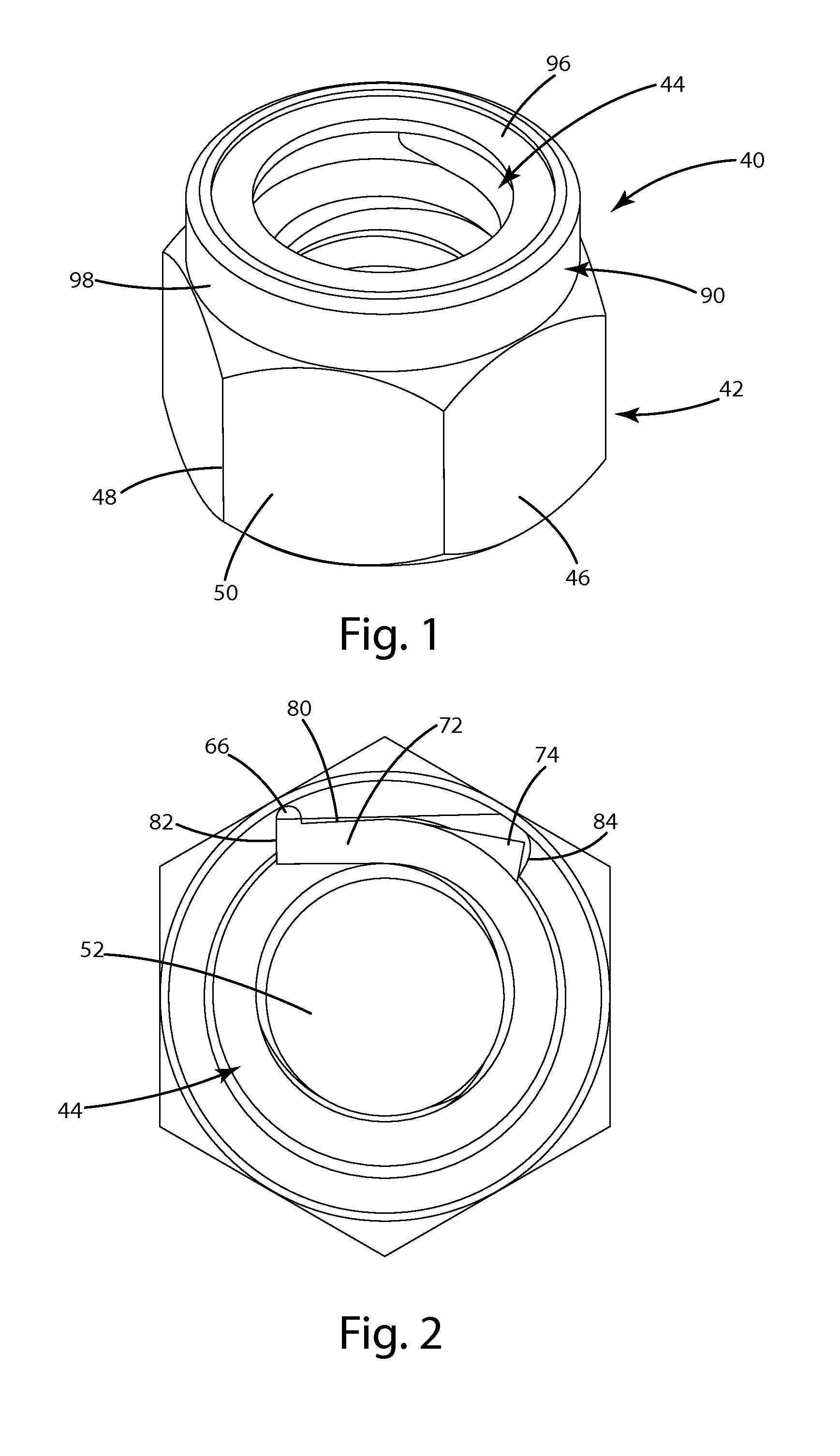
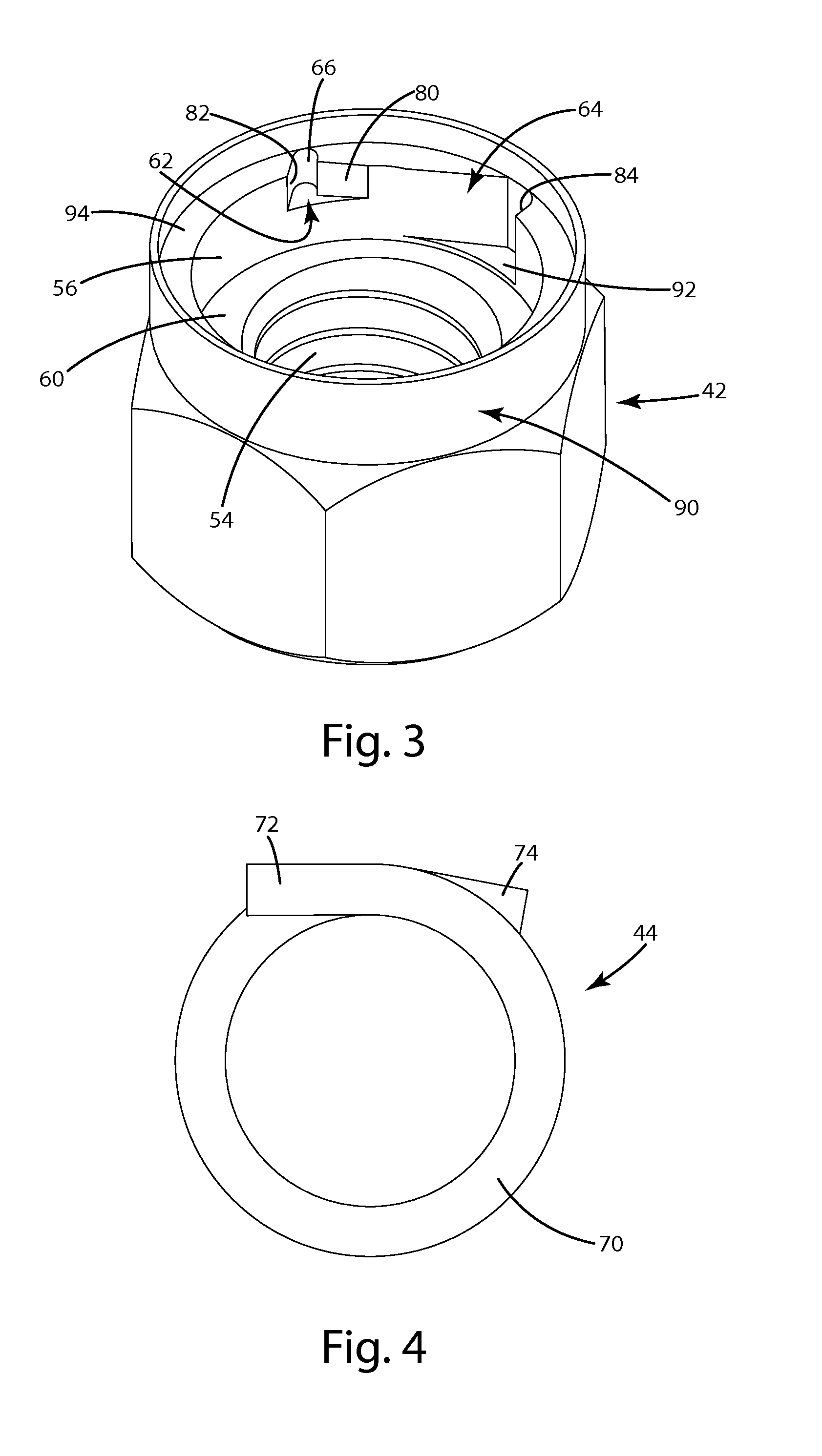
[0021]A locking threaded fastener constructed in accordance with a first embodiment of the invention is illustrated in FIGS. 1-5 and generally designated 40. Though shown in FIGS. 1-5 as a retaining nut or a lock nut, the concepts of the present invention can be incorporated into a variety of fasteners as will be recognized by those skilled in the art.

[0022]The threaded fastener 40 includes a body 42 and a locking element, spring, or band 44. The body 42 includes a hex-shaped outer portion 46 configured to be engaged and driven by a conventional driving tool (not shown). The hex-shaped portion 46 includes a plurality of corners 48 and a plurality of flats 50 extending therebetween. Alternatively, the body 42 may be square, otherwise polygonal, or any other shape. The body 42 may also be shaped to be engaged by any conventional driving tool, now known or later developed.

[0023]The body 42 defines a bore 52, which is at least partially threaded along its length. As p...

second embodiment

II. Second Embodiment

[0040]A locking threaded fastener constructed in accordance with a second embodiment of the invention is illustrated in FIGS. 6-10 and generally designated 140. The threaded fastener 140 is structurally and functionally similar to the previously described threaded fastener 40. Consequently, each element of the threaded fastener 140 is identified by the same designating numeral as the corresponding element in the threaded fastener 40 with the exception that the numeral begins with a 1. For example, the locking band 144 in the threaded fastener 140 corresponds to the locking band 44 in the threaded fastener 40. Only the elements that differ significantly are described below.

[0041]As shown in FIGS. 7-9, the threaded fastener 140 includes a first recess 162 and a second recess 164 with different sizes and shapes than the recesses 62, 64 in the first embodiment. The different recesses 162, 164 may result in a different removal torque for the threaded fastener 140. Fo...

third embodiment

III. Third Embodiment

[0042]A locking threaded fastener constructed in accordance with a third embodiment of the invention is illustrated in FIG. 11 and generally designated 240. The threaded fastener 240 is structurally and functionally similar to the previously described threaded fastener 40. Consequently, each element of the threaded fastener 240 is identified by the same designating numeral as the corresponding element in the threaded fastener 40 with the exception that the numeral begins with a 2. Only the elements that differ significantly are described below.

[0043]The threaded fastener 240 includes a cover 296 that encloses the locking element 244. As shown in FIG. 11, the cover 296 includes a lip portion 220 and a cover portion 222. To accommodate the portion of a threaded member 245 extending through the threaded fastener 240, the cover portion 222 may extend outward away from the lip portion 220. The distance the cover portion 222 extends away from the lip portion 220 may b...


PUM


Abstract

A locking fastener includes a fastener body, a locking band within the fastener body, and a retainer secured to the fastener body to retain the locking band within the fastener body. The locking band includes first and second tangs that fit within recesses in the fastener body to limit angular movement of the tangs. The tangs and the recesses are dimensioned to control the torque required to remove the fastener from a threaded member. The retainer defines a central circular hole corresponding to the diameter of a threaded member on which the fastener is mounted.

Description

BACKGROUND OF THE INVENTION[0001]The present invention relates to locking threaded fasteners, and more particularly to lock nuts that include a spring coil or band as a locking element.[0002]Lock nuts can include a spring coil or band as a locking element. Typically, the locking element includes one end bent radially outwardly and anchored with respect to the nut, for example, with the bent end fitted within a slot in the nut. Under loosening torque, the nut creates a tension load on the locking element, which causes the element to tighten its grip to prevent unintended relative rotation (i.e. loosening). The opposite force, compression, is created on the locking element during tightening (i.e. installation), which causes the locking element to loosen its grip so that there is relatively low installation torque.[0003]This locking system typically requires special tools or other means to enable removal of the nut. However, a number of lock nuts do not require special tools, for examp...

Claims


Application Information

Patent Timeline
Patent Type & Authority Patents(United States)
IPC IPC(8): F16B39/34F16B39/20
CPCF16B39/34F16B37/12F16B39/20
Inventor CAMPAU, DANIEL, N.
Owner FLOW RITE CONTROLS
Learn More