Surgical console

a surgical console and console technology, applied in the field of vitreoretinal surgery, can solve the problems of loss of vision, gas loss, waste of time,

Active Publication Date: 2014-06-10
ALCON INC
View PDF20 Cites 3 Cited by
  • Summary
  • Abstract
  • Description
  • Claims
  • Application Information

AI Technical Summary

Problems solved by technology

Both of these conditions result in a loss of vision.
The process of filling the syringe with gas is currently time consuming.
Often times, the coordination of activity between the two individuals results in the loss of gas and a waste of time, and, possibly, the violation of the sterile field.

Method used


Image

  • Surgical console
  • Surgical console

Examples


Embodiment Construction

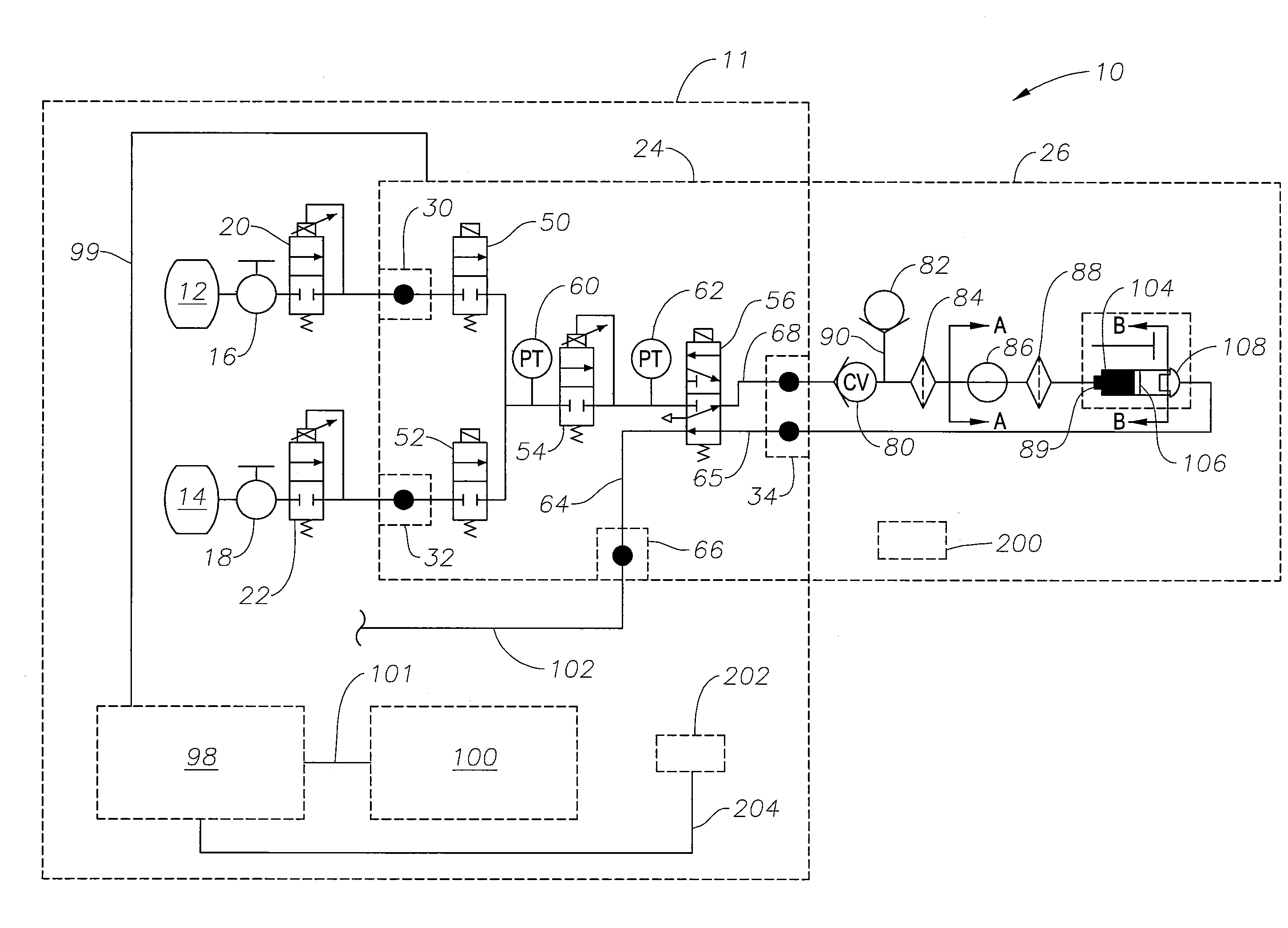
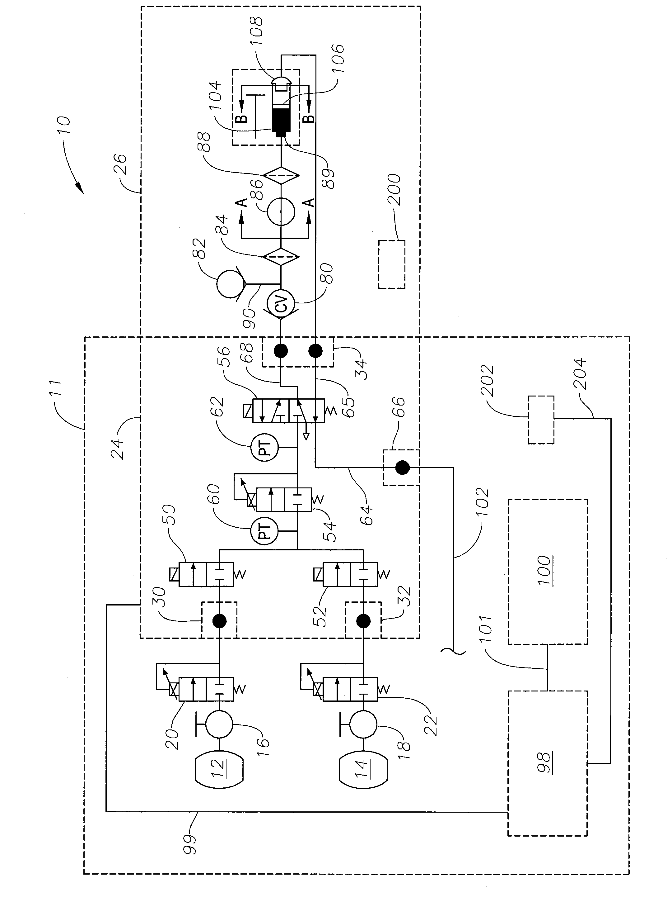
[0011]The preferred embodiments of the present invention and their advantages are best understood by referring to FIG. 1 of the drawings. Surgical system 10 generally includes a surgical console 11 and an automatic gas filling consumable 26. Surgical system 10 is preferably an ophthalmic surgical system.

[0012]Surgical console 11 preferably includes a pressurized gas bottle 12 having an integral valve 16 and regulator 20, a pressurized gas bottle 14 having an integral valve 18 and regulator 22, an automatic gas filling module 24 having an automatic gas filling port 34, a microprocessor 98 electrically coupled to automatic gas filling module 24 via an interface 99, a graphical user interface 100 electrically coupled to microprocessor 98 via interface 101, and a pressurized air line 102 capable of providing pressurized air in a proportional manner. Pressurized gas bottle 12 preferably holds a first retinal tamponading gas such as, by way of example, C3F8. Pressurized gas bottle 14 pref...


PUM

PropertyMeasurementUnit
transparentaaaaaaaaaa
intraocular pressureaaaaaaaaaa
timeaaaaaaaaaa

Abstract

A surgical console having bottles containing retinal tamponading gases and an automatic gas filling module disposed therein for filling an automatic gas filling consumable is disclosed. The automatic gas filling module includes a pair of gas shutoff valves and a regulator connected in series with a port for connection to the automatic gas filling consumable.

Description

[0001]This application claims the priority of U.S. Provisional Application Ser. No. 60 / 845,387 filed on Sep. 18, 2006.FIELD OF THE INVENTION[0002]The present invention generally pertains to vitreoretinal surgery and more particularly to improved systems for helping to perform fluid exchanges typically used in such surgeries.DESCRIPTION OF THE RELATED ART[0003]In a healthy human eye, the retina is physically attached to the choroid in a generally circumferential manner behind the pars plana. The vitreous humor, a transparent jelly-like material that fills the posterior segment of the eye, helps to cause the remainder of the retina to lie against, but not physically attach, to the choroid.[0004]Sometimes a portion of the retina becomes detached from the choroid. Other times a portion of the retina may tear, allowing vitreous humor, and sometimes aqueous humor, to flow between the retina and the choroid, creating a build up of subretinal fluid. Both of these conditions result in a loss...

Claims


Application Information

Patent Timeline
Patent Type & Authority Patents(United States)
IPC IPC(8): B05B5/16
CPCF17C2223/035B65B3/003A61M2205/3331F17C2223/0123F17C2225/0123A61M2205/6054F17C2225/035A61M13/003A61M2209/045A61F9/00736A61M2205/073F17C2205/058F17C2270/02F17C2250/032
Inventor HOPKINS, MARK A.HUCULAK, JOHN C.TURNER, DENIS P.
Owner ALCON INC
Why Eureka
Try Eureka