Control system for NOx removal device, NOx removal device provided with the same, boiler plant provided with the same, and method of controlling NOx removal device

a control system and nox removal technology, which are applied in the direction of biological material analysis, machine/engine, process and machine control, etc., can solve the problems of inferior efficiency of nox removal devices, and achieve excellent nitrogen oxide removal, simplified maintenance, and enhanced plant operation.

Active Publication Date: 2014-06-10
MITSUBISHI POWER LTD
View PDF17 Cites 2 Cited by
  • Summary
  • Abstract
  • Description
  • Claims
  • Application Information

AI Technical Summary

Benefits of technology

[0026]With this boiler plant, because the NOx removal device that can prevent the reagent unused in the reactions from flowing out is employed, it is possible to prevent the reagent from forming deposits at the heat exchanger to which the fluid is guided from the NOx removal device, thus blocking the heat exchanger. Therefore, the reliability of the plant operation can be enhanced, and the maintenance thereof can be simplified.
[0027]In addition, because the NOx removal device that achieves excellent nitrogen oxide removal is employed, it is possible to considerably reduce the nitrogen oxides that flow out from the boiler plant. Therefore, it is possible to provide a boiler plant with a low environmental load.

Problems solved by technology

Hei 7-60066 and Japanese Unexamined Patent Application, Publication No. 2003-290630, there is a problem in that the concentration distribution of the reducing agent does not reach a desired concentration distribution when a nozzle, etc. is blocked, even in the case in which the spraying level of the reducing agent is kept constant, and that the efficiency of the NOx removal devices consequently becomes inferior.

Method used


Image

  • Control system for NOx removal device, NOx removal device provided with the same, boiler plant provided with the same, and method of controlling NOx removal device
  • Control system for NOx removal device, NOx removal device provided with the same, boiler plant provided with the same, and method of controlling NOx removal device
  • Control system for NOx removal device, NOx removal device provided with the same, boiler plant provided with the same, and method of controlling NOx removal device

Examples


first embodiment

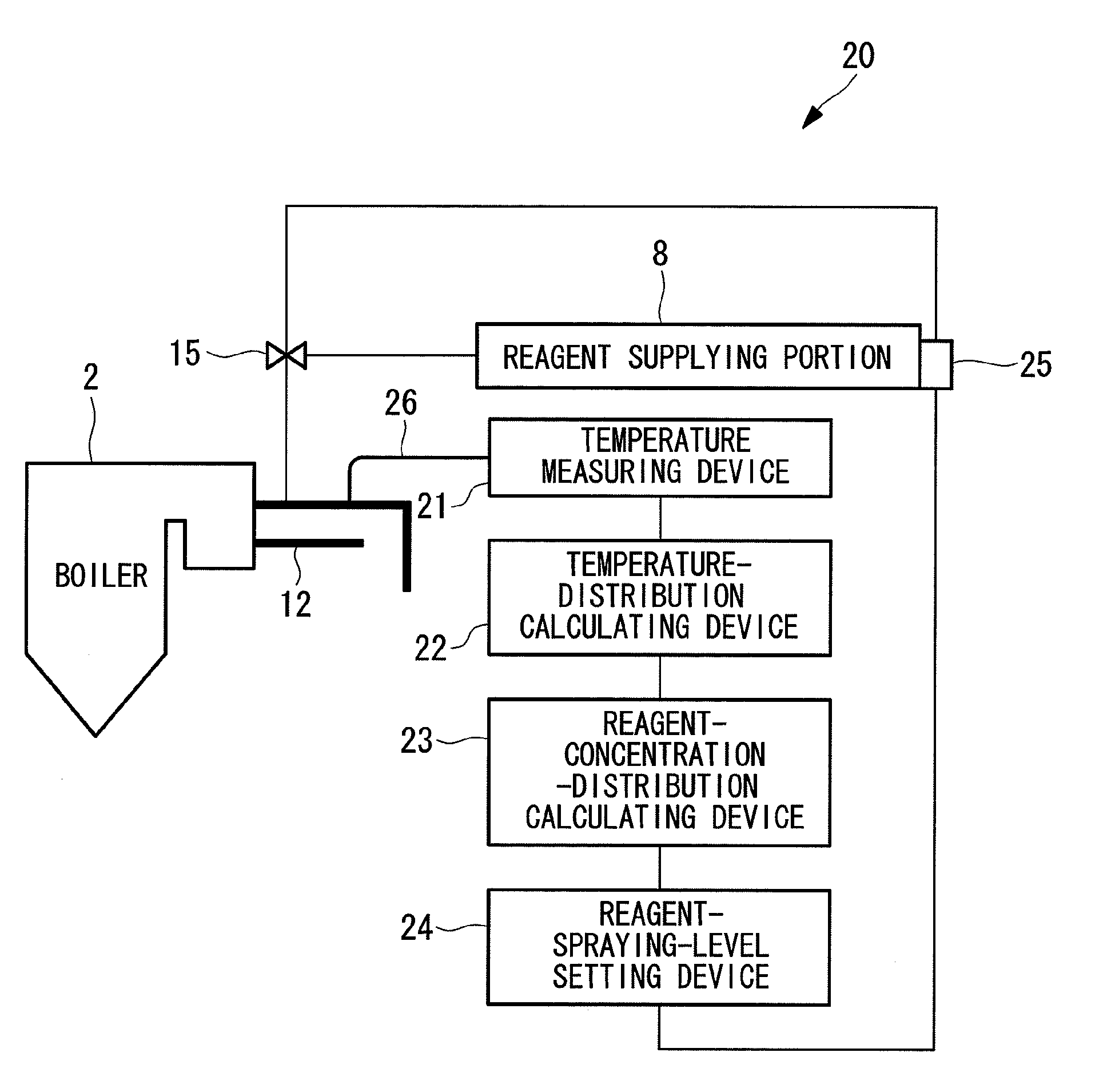
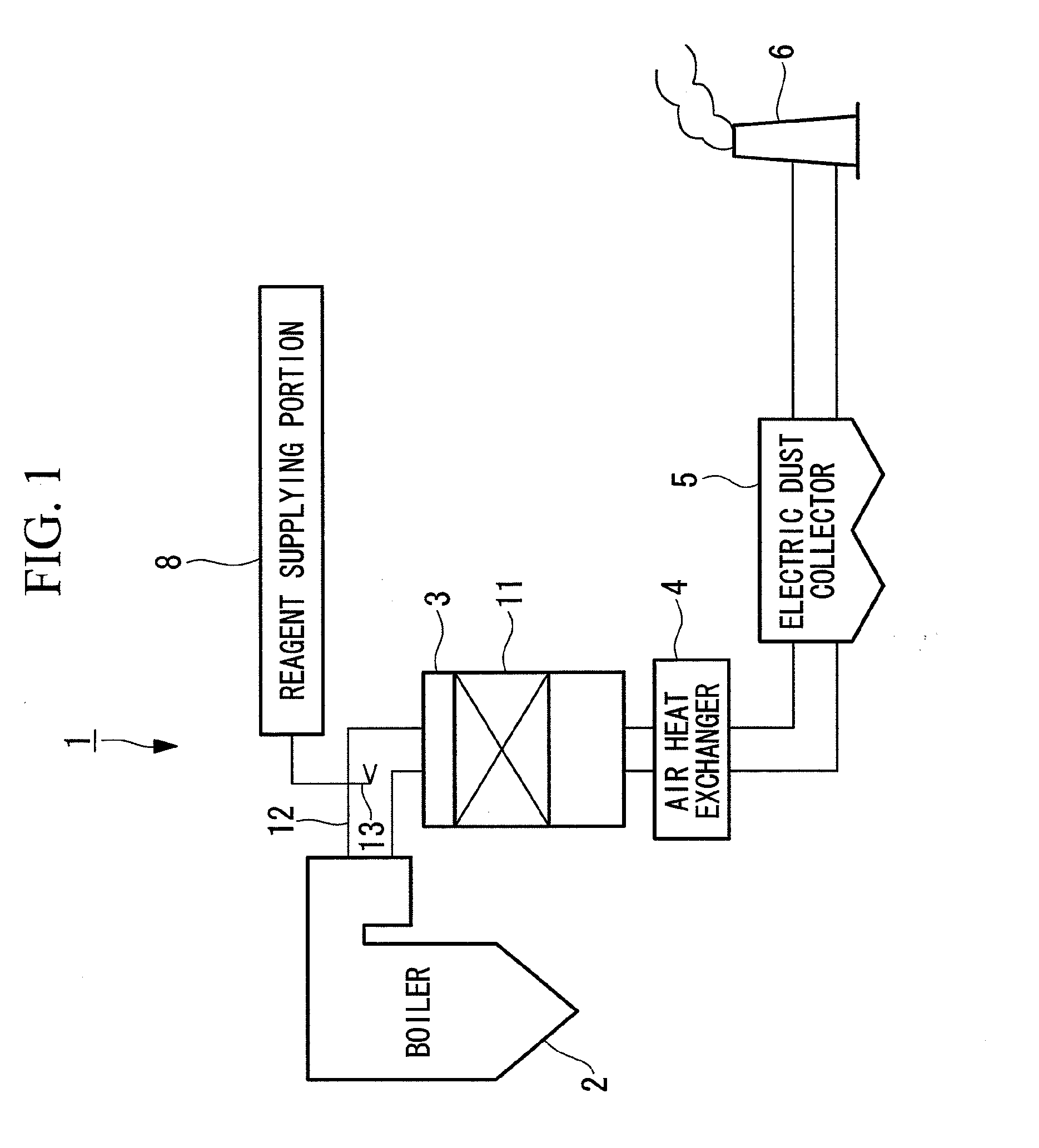
[0043]FIG. 1 is a configuration diagram showing, in outline, a boiler plant according to this embodiment.

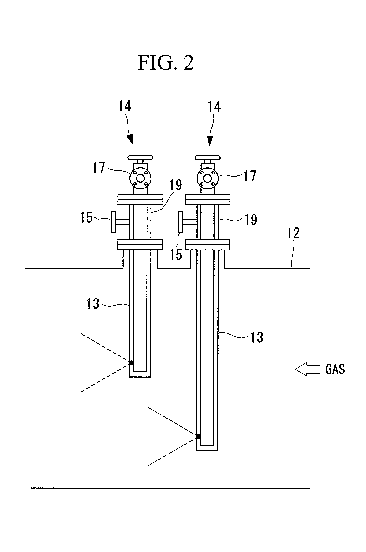
[0044]A boiler plant 1 is provided with a boiler 2 that discharges exhaust gas (fluid), a NOx removal device 3 to which the exhaust gas discharged from the boiler 2 is guided, an air heat exchanger (heat exchanger) 4 in which the exhaust gas that has flowed out from the NOx removal device 3 undergoes heat exchange with air, an electric dust collector 5 that removes dust in the exhaust gas whose temperature is lowered at the air heat exchanger 4, and a chimney 6 through which the exhaust gas purified at the NOx removal device 3 and the electric dust collector 5 is guided outside the boiler plant 1.

[0045]The boiler 2 combusts fuel and discharges the exhaust gas. The air heat exchanger 4 uses air as coolant to perform heat exchange with the exhaust gas. By passing through the air heat exchanger 4, the temperature of the exhaust gas is lowered.

[0046]The electric dust collector 5 remo...

second embodiment

[0094]A second embodiment of the present invention will be described below. A control system of a NOx removal device according to this embodiment, a NOx removal device provided with the same, a boiler plant provided with the same, and a method of controlling a NOx removal device differ from those of the first embodiment in that reagent-concentration controlling means is provided, and other components are the same. Therefore, the same reference signs are given to the same structures and control methods, and descriptions thereof will be omitted.

[0095]FIG. 9 is a configuration diagram showing, in outline, a NOx removal device provided with the reagent-concentration controlling means according to the second embodiment of the present invention.

[0096]Here, a two-liquid mixed system is employed for ammonia (reagent) which is the reducing agent, wherein ammonia, which is a base liquid, is mixed with dilution water (diluting agent) for diluting the base liquid. The concentration of the ammon...

third embodiment

[0120]A third embodiment of the present invention will be described below. A control system of a NOx removal device according to this embodiment, a NOx removal device provided with the same, a boiler plant provided with the same, and a method of controlling a NOx removal device differs from those of the first embodiment in that ammonium chloride solution is used as the reducing agent, and other components are the same. Therefore, the same reference signs are given to the same structures and control methods, and descriptions thereof will be omitted.

[0121]FIG. 13 is a configuration diagram showing, in outline, a boiler plant provided with a NOx removal device according to the third embodiment of the present invention.

[0122]The NOx removal device 3 is provided with a NOx removal catalyst 11a and a mercury-oxidizing catalyst 11b as the catalysts 11. Ammonium chloride solution is used as the reducing agent (reagent).

[0123]A SOx removal device 7 removes sulfur contained in the exhaust gas...


PUM

PropertyMeasurementUnit
temperature measuringaaaaaaaaaa
temperature distributionaaaaaaaaaa
concentrationaaaaaaaaaa

Abstract

A control system of a NOx removal device is provided with reagent introducing means for introducing a reagent into a fluid, a temperature measuring device that measures a temperature distribution of the fluid, a reagent-concentration calculating portion that calculates a concentration distribution of the reagent introduced into the fluid with the temperature distribution determined at the temperature measuring device, a reagent-flow-rate determining portion that determines a flow rate of the reagent that the reagent introducing means introduces in accordance with the concentration distribution calculated at the reagent-concentration calculating portion, and a reagent-introducing-means control portion that controls the reagent introducing means so as to introduce the reagent into the fluid at the flow rate determined at the reagent-flow-rate determining portion.

Description

TECHNICAL FIELD[0001]The present invention relates to a control system for a NOx removal device, a NOx removal device provided with the same, a boiler plant provided with the same, and a method of controlling a NOx removal device, and it relates particularly to control of the concentration distribution of a reducing agent sprayed into exhaust gas.BACKGROUND ART[0002]Generally in a NOx removal device, a reducing agent is sprayed into exhaust gas in a smoke path, and nitrogen oxides contained in the exhaust gas are removed in the form of nitrogen and water by means of chemical reactions with a catalyst. The reducing agent sprayed into the exhaust gas evaporates, and the temperature of the exhaust gas is reduced at this time due to the latent heat of evaporation.[0003]The spraying conditions of the reducing agent are adjusted by measuring the temperature of the exhaust gas into which the reducing agent is sprayed during a trial operation of the boiler plant. The NOx removal device is e...

Claims


Application Information

Patent Timeline
Patent Type & Authority Patents(United States)
IPC IPC(8): B01D53/90G01N33/00B01D53/56
CPCB01D2251/2062B01D53/90B01D53/8625B01D2258/0283B01D53/8631B01D53/56B01D53/8696Y10T436/177692Y10T436/17Y10T436/179228Y10T436/12
Inventor YAMAURA, TAKETOSHIDEGUCHI, YOSHIHIROUKAI, NOBUYUKIOKINO, SUSUMUNAGAYASU, TATSUTO
Owner MITSUBISHI POWER LTD
Why Eureka
Try Eureka