
Pneumatic tire with tread having land portions defining drop lengths

a technology of pneumatic tires and land portions, applied in the field of pneumatic tires, can solve the problems of not necessarily improving handling performance, and achieve the effect of improving handling and stability

Active Publication Date: 2014-06-17
THE YOKOHAMA RUBBER CO LTD
View PDF15 Cites 0 Cited by
  • Summary
  • Abstract
  • Description
  • Claims
  • Application Information

AI Technical Summary

Benefits of technology

[0009]Under such circumstances, it is an object of the present invention to improve handling and stability including handling performance in a pneumatic tire having an asymmetric tread pattern.
[0017]According to the pneumatic tire of the invention, it is possible to improve the handling and stability including the handling performance in the pneumatic tire having the asymmetric tread pattern.

Problems solved by technology

However, in the above-described tire, the handling performance is not necessarily improved in some cases.

Method used


Image

  • Pneumatic tire with tread having land portions defining drop lengths
  • Pneumatic tire with tread having land portions defining drop lengths
  • Pneumatic tire with tread having land portions defining drop lengths

Examples


example

Patterns 1 to 6 and Prior-Art Pattern

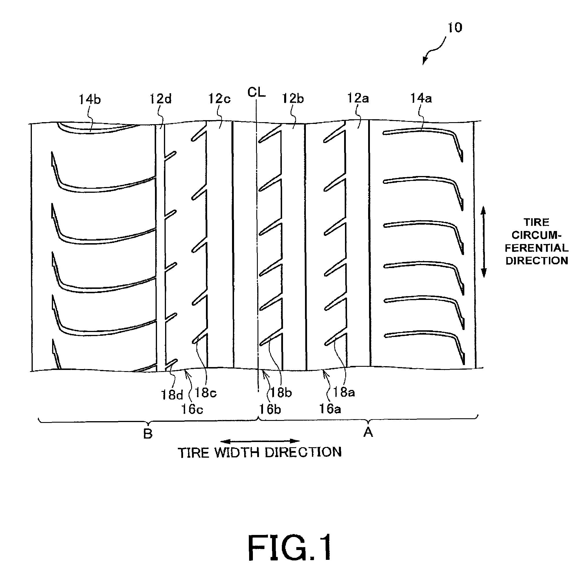
[0048]As patterns 1 to 6 and a conventional pattern, the tread pattern illustrated in FIG. 1 was used. The patterns 1 to 6 were different from each other in drop lengths of edge portions. Tire circumferential grooves 12a, 12b, 12c, and 12d had groove depths GD of 8.2 mm.

[0049]In the conventional pattern, a profile of a land portion was not in a protruding shape but in a flat shape. Therefore, drop lengths of edge portions were almost zero.

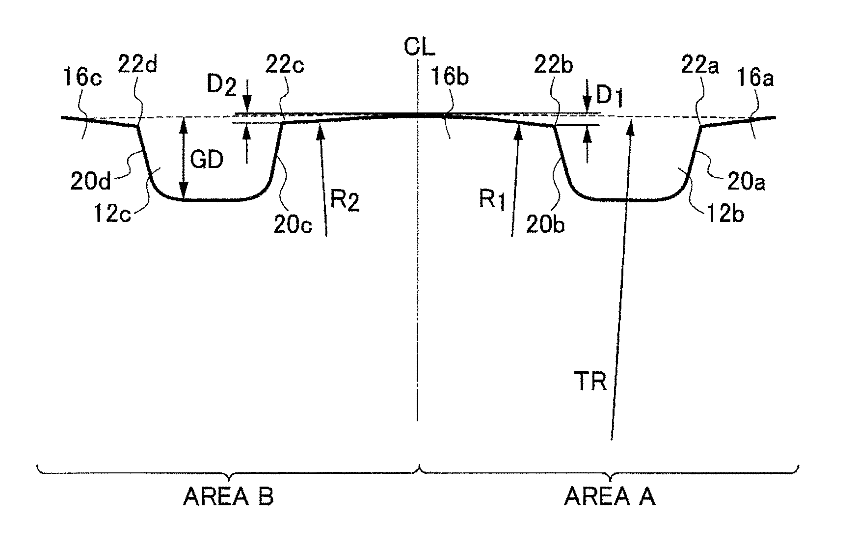
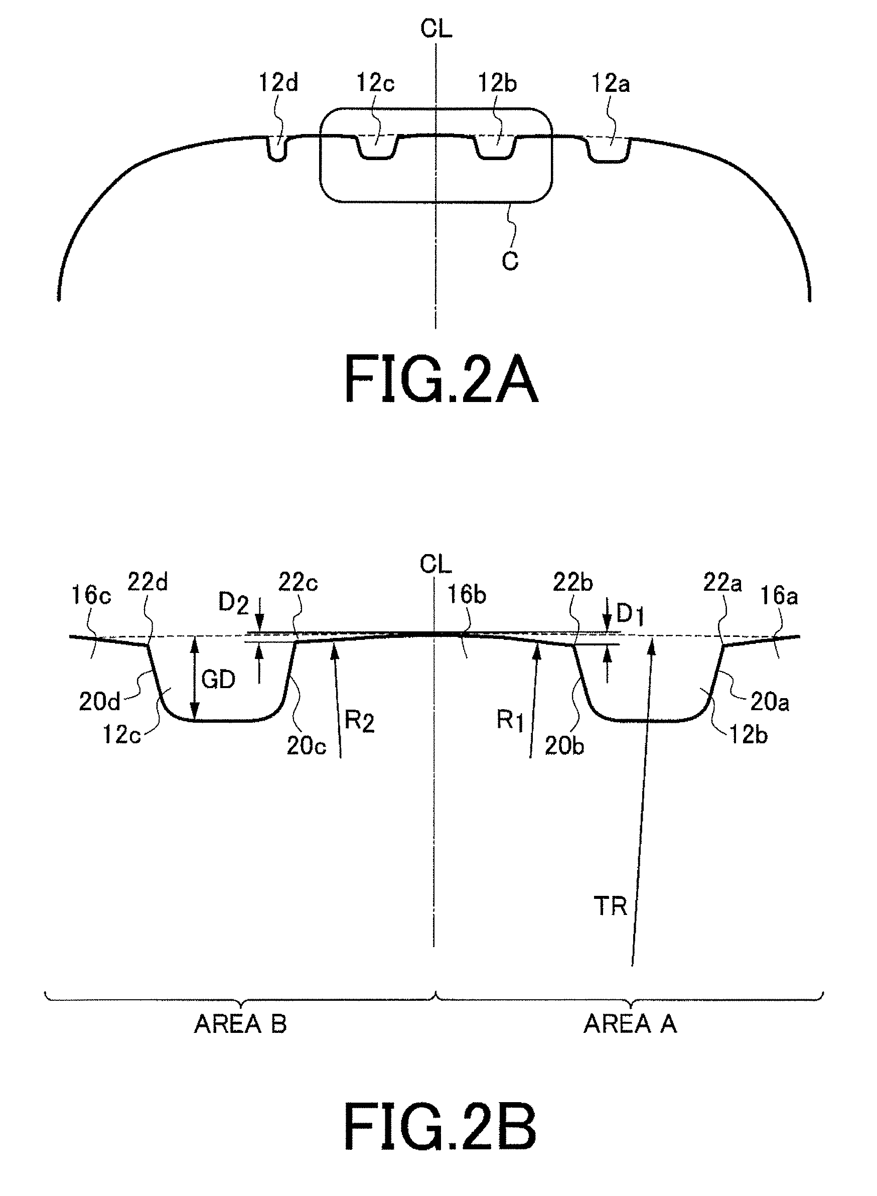
[0050]The drop lengths D1 of the edge portions of the patterns 1 to 3 were 0.01 times, 0.03 times, 0.08 times the groove depths GD of the tire circumferential grooves 12a, 12b, 12c, and 12d. On the other hand, the drop lengths D2 of the edge portions were set to smaller values than the drop lengths D1 of the edge portions and the drop lengths D2 of the edge portions were 0.6 times the drop lengths D1 of the edge portions.

[0051]The drop lengths D1 of the edge portions in the pattern 4 were −0.03 times the groove ...

examples

Pattern 2, Patterns 7 to 12

[0057]As patterns 7 to 12, the tread pattern illustrated in FIG. 1 was used. In the patterns 7 to 12, the drop lengths D1 and D2 of the edge portions were identical with each other and the radiuses R1 and R2 of curvature were different from each other.

[0058]To put it concretely, the drop lengths D1 of the edge portions in the patterns 7 to 12 were 0.03 times the groove depths GD of the tire circumferential grooves 12a, 12b, 12c, and 12d. On the other hand, the drop lengths D2 of the edge portions were 0.018 times the groove depths GD. The ratio of the radiuses R1 and R2 of curvature to the radius TR of curvature of the tread profile shape was changed between 0.04 and 0.16. The radius TR of curvature of the tread profile shape is a radius obtained by approximating the tread profile shape by a single circular arc having a center located on the tire center line CL. At this time, an error between the arc and the tread profile shape is 0.5 mm or smaller.

[0059]T...


PUM


Abstract

The pneumatic tire includes a tread pattern having a land portion sandwiched between tire circumferential grooves. A groove area ratio of the tread pattern is different between areas on opposite sides with reference to a tire center line in a tire width direction. A first side has the larger groove area ratio and a second side has the smaller groove area ratio respectively. The land portion is protruding outward in a tire radial direction and the land portion has edge portions bordering the tire circumferential grooves and formed by groove walls of the tire circumferential grooves sandwiching the land portion and a surface of the land portion. A drop length of the edge portion facing to the first side from a most protruding point of the land portion along the tire radial direction is longer than a drop length of the edge portion facing to the second side.

Description

BACKGROUND OF THE INVENTION[0001]1. Field of the Invention[0002]The present invention relates to a pneumatic tire.[0003]2. Description of the Related Art[0004]Recently, in a tire market, e.g., the European market, there is a need for improvement of handling and stability including handling performance, high-speed lane changing performance, and the like of a pneumatic tire (hereafter referred to as “tire”), as performance of vehicles increases. For the improvement of the handling and stability, a tire having an asymmetric tread pattern and continuously extending land portions has been proposed. When the tire having the asymmetric tread pattern is mounted to the vehicle, the tire is disposed so that the tire tread pattern has a smaller groove area ratio on the outside portion of a tread area, the outside portion having a significant influence on the handling and stability, and a larger groove area ratio on the inside portion of the tread area. In this way, the tire having the asymmetr...

Claims


Application Information

Patent Timeline
Patent Type & Authority Patents(United States)
IPC IPC(8): B60C11/03
CPCB60C11/1392B60C2011/0388B60C2011/0383B60C11/033B60C11/0304B60C11/1376
Inventor MITA, MASAYA
Owner THE YOKOHAMA RUBBER CO LTD
Learn More