
Overvoltage protection element

a protection element and overvoltage protection technology, applied in the direction of overvoltage protection resistors, resistor housings/enclosements/embeddings, emergency protective arrangements for limiting excess voltage/current, etc., can solve the problem of unwanted increase of leakage current of varistor at operating voltage, damage of components within the overvoltage protection element or the overvoltage protection element overall, and the plastic housing surrounding the varistor is not easily accessible and easily damaged. , to achieve th

Inactive Publication Date: 2014-07-01
PHOENIX CONTACT GMBH & CO KG
View PDF18 Cites 5 Cited by
  • Summary
  • Abstract
  • Description
  • Claims
  • Application Information

AI Technical Summary

Benefits of technology

This configuration achieves a low noise level, durability, and simplicity in design by balancing varistor thickness tolerances, reducing the risk of arcs and overheating, while maintaining effective overvoltage protection and reducing the risk of system damage.

Problems solved by technology

Due to aging and temporarily occurring overvoltages (TOV) in the range of seconds, an unwanted increase of the leakage current of the varistor at operating voltages occurs, especially in overvoltage protection elements with a varistor as the arrester.
When the varistor overheats, for example due to a leakage current which has occurred, a solder connection provided between the varistor and a disconnection means is broken, which leads to electrical disconnection of the varistor.
The disadvantage in the known overvoltage protection devices and overvoltage protection elements is, however, that each contact opening under operating voltages of greater than 30 volts and high current loads can produce an arc.
Thus, when the solder connection is broken an arc can occur between the varistor and the separation means, which can lead to damage of components within the overvoltage protection element or of the overvoltage protection element overall, and especially of the plastic housing surrounding the varistor.
Since several of these overvoltage protection elements or overvoltage protection devices are often arranged several next to one another and to other electronic devices, adjacent overvoltage protection devices or other electronic devices can often by destroyed or damaged due to an arc which occurs within the housing.
The electrical contact-making of the varistor and its arrangement in the housing and the arrangement and configuration of the electrodes make the structure and the mounting of the known overvoltage protection device, however, relatively complex.
Depending on the actual thickness of the two varistors, however, different contact forces arise and, as a result, adversely affect the reliable and continuous operation of the overvoltage protection element under certain circumstances.
Moreover the use of elastic contact elements has a disadvantage due to the impedance of the elastic contact elements, which increases the impedance of the electrical connection to the varistors, and thus also raises the possible noise level.

Method used


Image

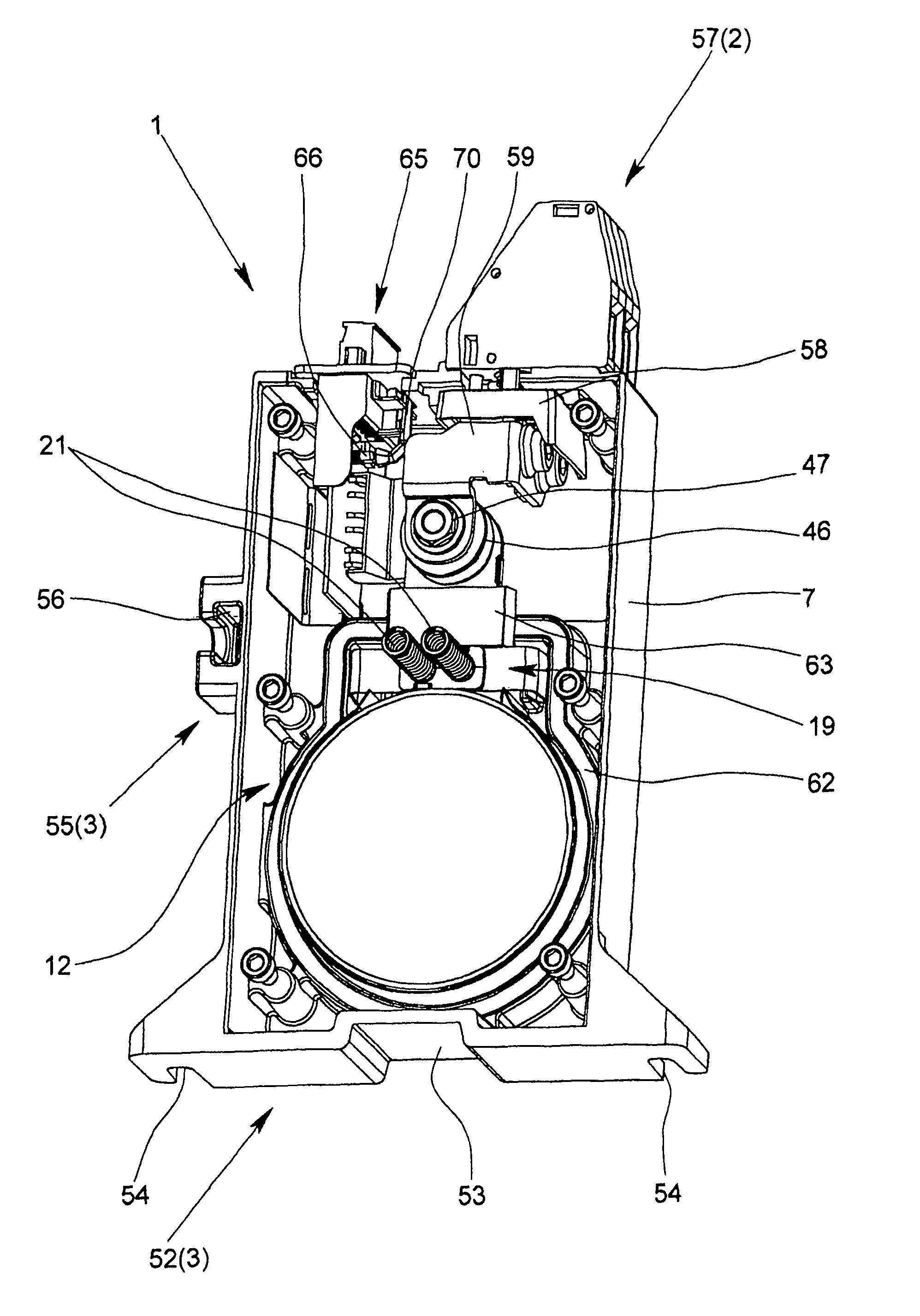
  • Overvoltage protection element
  • Overvoltage protection element
  • Overvoltage protection element

Examples


first embodiment

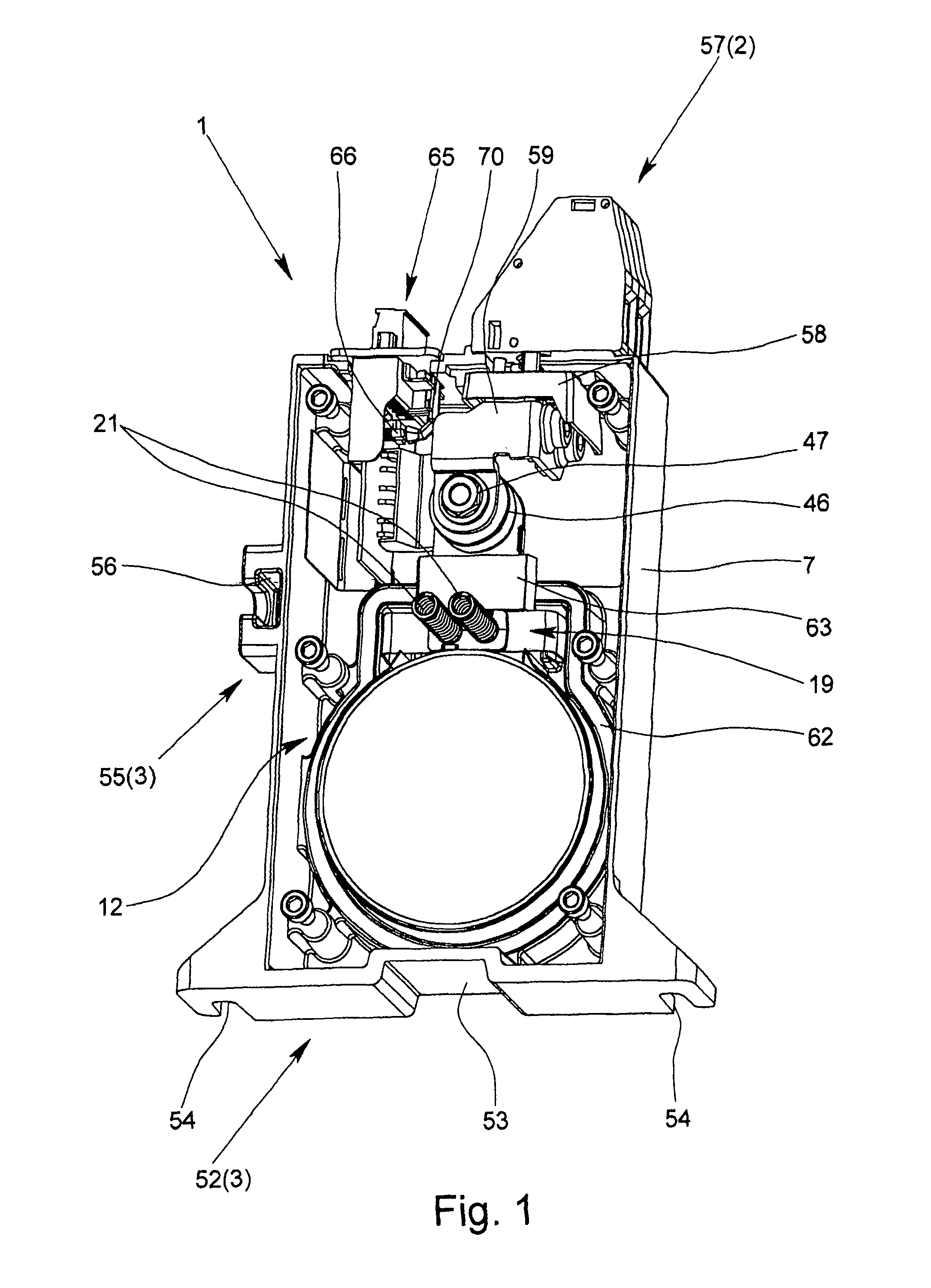
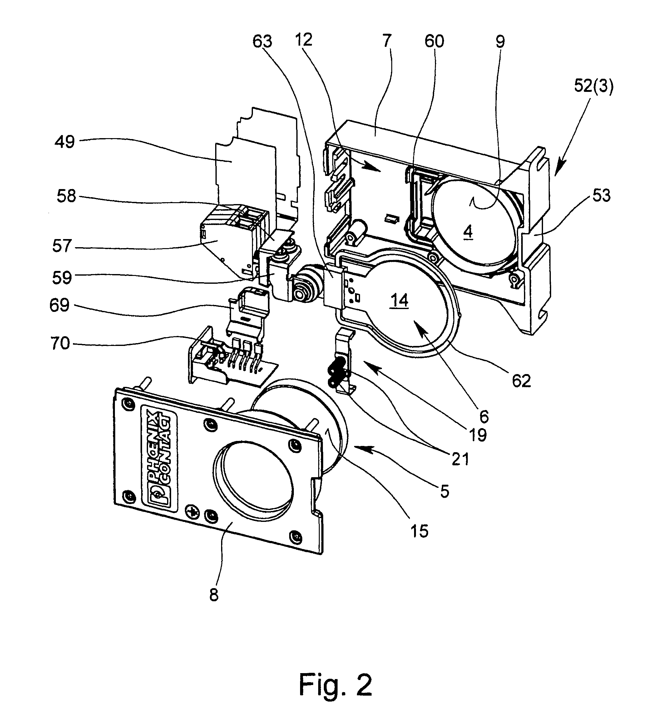
[0058]In the first embodiment according to FIGS. 1, 2, 3a, and 3b, within the housing there is only one short circuit switch which has a shorting jumper 19, an insulating retaining element 20 which is mechanically connected to the shorting jumper 19, two spring elements 21 and one retaining metal 22. In the normal state of the varistors 4, 5 which is shown in FIG. 3a, the shorting jumper 19 is located spaced apart from the middle electrode 6, although the retaining element 20 is exposed to a spring force in the direction to the middle electrode 6 by the spring elements 21 which are compressed against their spring force. In the normal state of the varistors 4, 5 the shorting jumper 19 is kept in the first position spaced apart from the middle electrode 6 such that the retaining element 20 is supported with a spacer element 24 which projects through an opening 23 in the middle electrode 6 on the retaining metal 22, which is connected to the bottom of the middle electrode 6 via a solde...

second embodiment

[0063]In the second embodiment according to FIGS. 5 and 6, one short-circuit switch at a time is assigned to the two varistors 4, 5. In this embodiment the middle electrode 6 is connected to a connection electrode 30, which is guided through one housing penetration 31 insulated into the housing interior. The middle electrode 6 can be connected to an active conductor via the connecting electrode 30. The second connecting regions 15 of the two varistors 4, 5 each make contact with the connecting metal 32 which is located on the side of the varistors 4, 5 facing away from the middle electrode 6. Between the housing halves 7, 8 and the connecting metals 32 there is one insulating element 33 at a time which can be formed for example by a silicone film or an insulating paper, as a result of which the two connecting metals 32 are insulated relative to the housing halves 7, 8.

[0064]The two short-circuit switches have a flexible conductor section 34, an actuating pin 35 and a spring element ...


PUM


Abstract

An overvoltage protection element is disclosed that includes a housing, connections for electrically connecting the overvoltage protection element to a current path or a signal path to be protected The overvoltage protection element further includes two varistors arranged inside the housing and electrically connected in parallel, and a center electrode arranged at least partially between the varistors. The housing has two housing halves made of metal and electrically connected to each other, wherein the center electrode is isolated from the housing halves and is electrically connected at the opposite sides of the electrode to a first connection area of a varistor and wherein the two varistors and the center electrode are sandwiched between the two housing halves. One housing half is designed as a cover, which has a covering section and a recessed engagement section. In the installed states of the two housing halves, the engagement section engages in the corresponding receiving space formed by the other housing half and the covering section covers the receiving space, and in that the two housing halves are connected to each other such that in the installed state a visible gap is present between the two housing halves.

Description

BACKGROUND OF THE INVENTION[0001]1. Field of the Invention[0002]The invention relates to an overvoltage protection element with a housing, terminals for electrical connection of the overvoltage protection element to a current path or a signal path to be protected, two varistors which are connected electrically in parallel and which are located within the housing, and a middle electrode located at least partially between the varistors. The housing has two metal housing halves which are electrically connected to one another. The middle electrode is insulated relative to the housing halves and electrically connected with its opposite sides to a first connecting region of a varistor. The two varistors and the middle electrode are sandwiched between the two housing halves.[0003]2. Description of Related Art[0004]Conventional electrical circuits and systems work without perturbations in the voltage specified for them (i.e., the rated voltage). This does not apply when overvoltages occur. ...

Claims


Application Information

Patent Timeline
Patent Type & Authority Patents(United States)
IPC IPC(8): H01C7/12H02H9/04H01C1/02
CPCH01C7/12H02H9/04H02H9/041H01C1/02H01C7/126H01T4/08
Inventor DEPPING, CHRISTIANGREWE, CHRISTINAWOSGIEN, JOACHIMJUNGERMANN, PHILIP
Owner PHOENIX CONTACT GMBH & CO KG
Learn More