Sheet supply device and image forming apparatus
a technology of image forming apparatus and supply device, which is applied in the direction of thin material handling, article separation, transportation and packaging, etc., can solve the problems of excessive thus deformation of separation unit, and achieve the effect of increasing the size of the image forming apparatus
- Summary
- Abstract
- Description
- Claims
- Application Information
AI Technical Summary
Benefits of technology
Problems solved by technology
Method used
Image
Examples
first embodiment
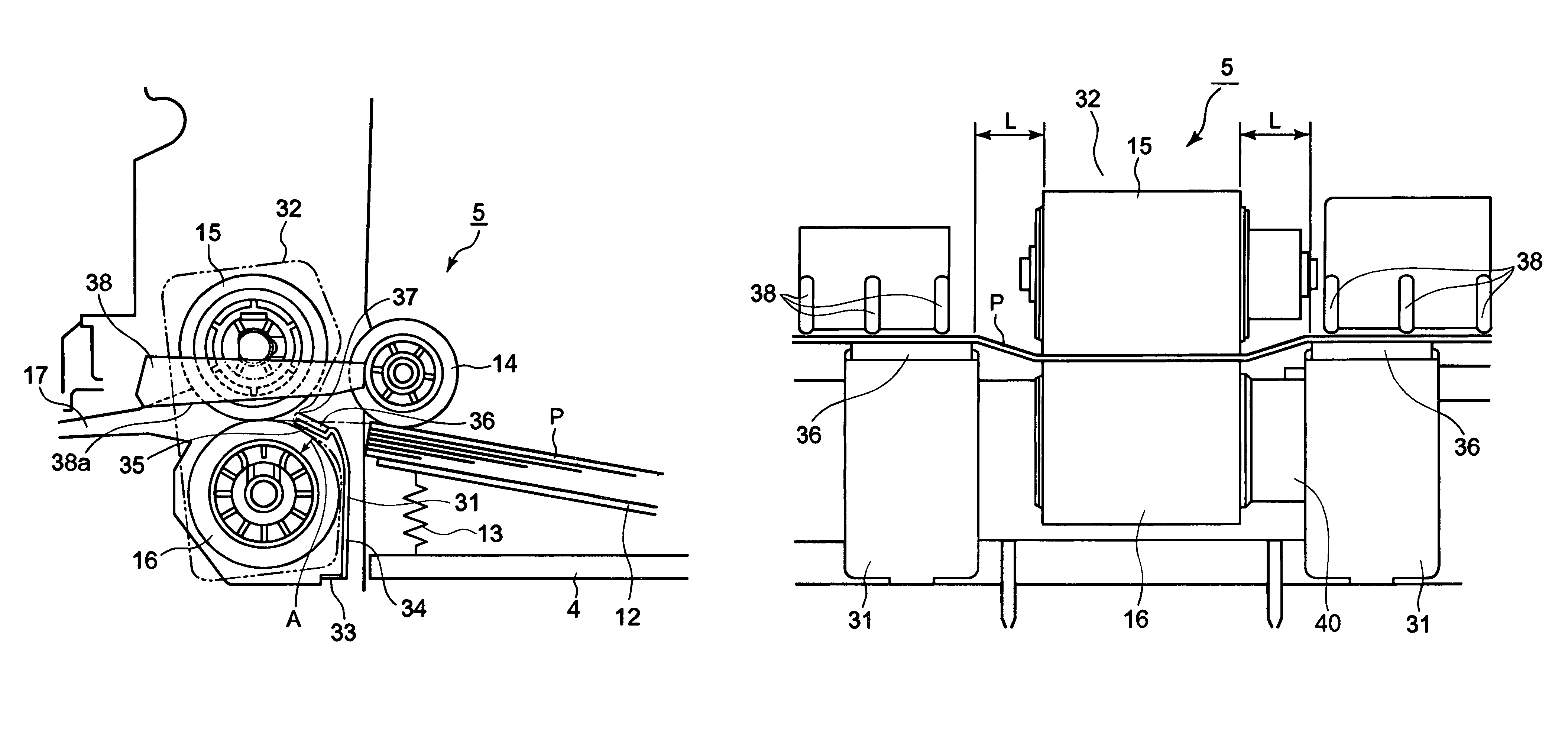
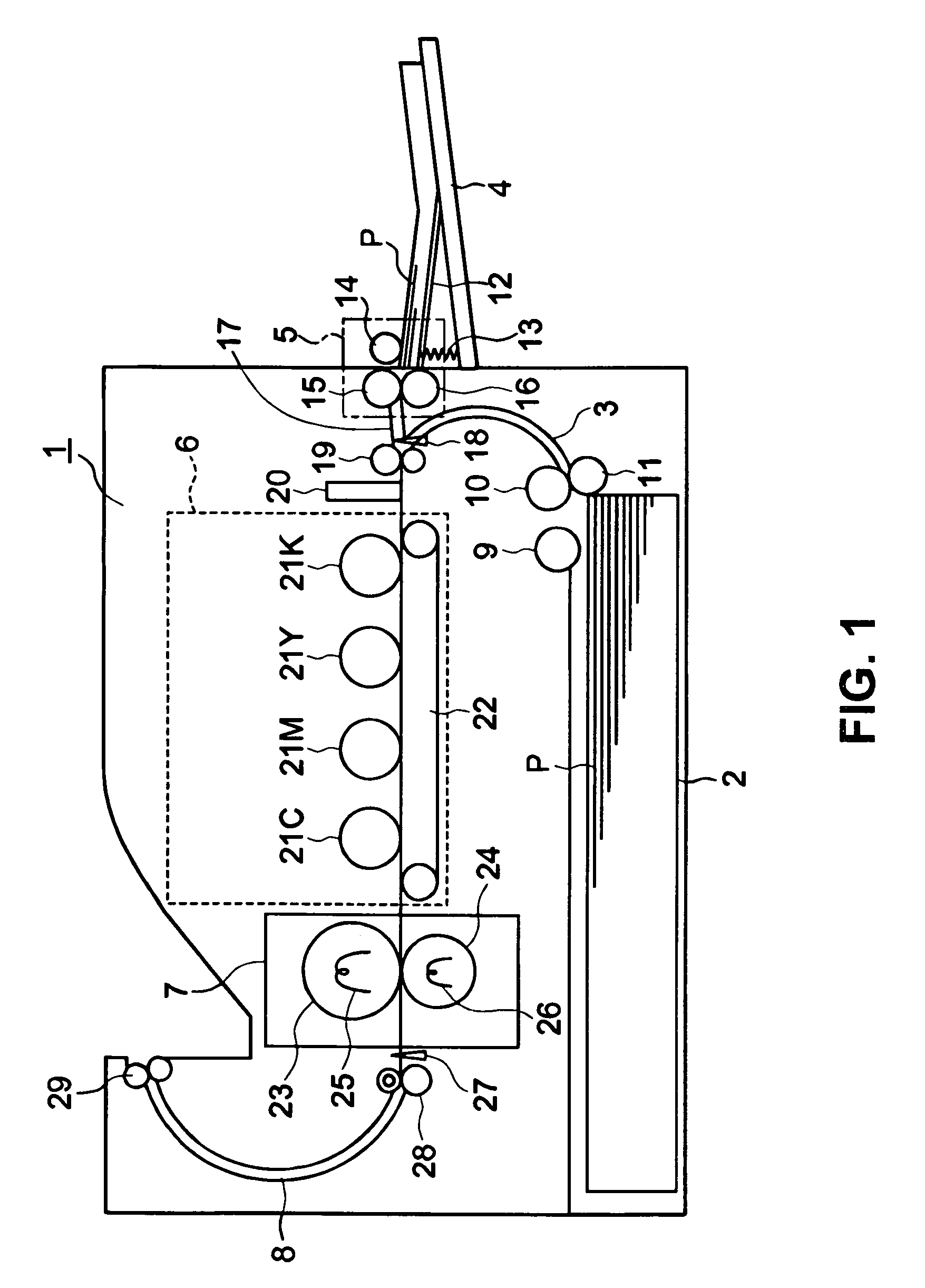
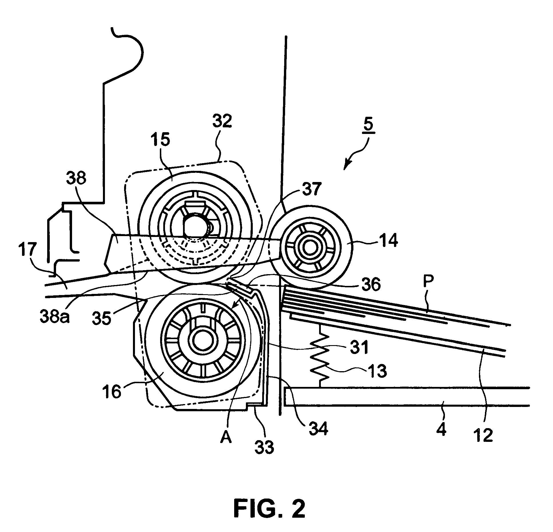
[0022]A first embodiment of the present invention will be explained. FIG. 1 is a schematic view showing an electro-photography printer 1 according to the first embodiment of the present invention.
[0023]As shown in FIG. 1, the electro-photography printer 1 as an image forming apparatus includes a medium cassette 2, a sheet supply transportation path 3, a medium tray 4, a sheet supply unit 5, an image forming unit 6, a fixing unit 7, and a discharge transportation path 8. A medium P is stored in the medium cassette 2, and a pressing member (not shown) presses the medium P against a pickup roller 9. A transportation roller 10 and a separation roller 11 are disposed on a right side (refer to FIG. 1) of the pickup roller 9 for separating the medium P picked up with the pickup roller 9 and for transporting the medium P into the sheet supply transportation path 3.
[0024]In the embodiment, the medium tray 4 is provided for supplying a long medium, a thin medium, a thick medium, or a narrow m...
second embodiment
[0056]A second embodiment of the present invention will be explained next. FIG. 4 is a schematic front view showing a sheet supply device or a sheet supply unit 51 according to the second embodiment of the present invention.
[0057]As shown in FIG. 4, similar to the first embodiment, the sheet supply unit 51 includes the sheet supply roller 14, the first separation units 31, and the second separation unit 32 (indicated with a phantom line). The second separation unit 32 is formed of a pair of the transportation roller 15 and the separation roller 16 pressed against with each other. The first separation units 31 are disposed outside the extension area of the second separation unit 32 in the medium transportation direction.
[0058]In the second embodiment, different from the first embodiment, transportation guides 52 are provided above the first separation units 31. The transportation guides 52 have lower portions 52a extending in substantially a horizontal direction such that a minimum s...
third embodiment
[0068]A third embodiment of the present invention will be explained next. FIG. 6 is a schematic front view showing a sheet supply device or a sheet supply unit 61 according to the third embodiment of the present invention.
[0069]As shown in FIG. 6, similar to the first and second embodiments, the sheet supply unit 61 includes the sheet supply roller 14, the first separation units 31, and the second separation unit 32 (indicated with a phantom line). The second separation unit 32 is formed of a pair of the transportation roller 15 and the separation roller 16 pressed against with each other. The first separation units 31 are disposed outside the extension area of the second separation unit 32 in the medium transportation direction.
[0070]In the third embodiment, different from the second embodiment, transportation guides 62 are provided above the first separation units 31. The transportation guides 62 have lower portions for guiding the leading edge of the medium P toward a nip portion...
PUM
 Abstract
Description
Claims
Application Information
 - R&D
- Intellectual Property
- Life Sciences
- Materials
- Tech Scout
- Unparalleled Data Quality
- Higher Quality Content
- 60% Fewer Hallucinations
Browse by: Latest US Patents, China's latest patents, Technical Efficacy Thesaurus, Application Domain, Technology Topic, Popular Technical Reports.
© 2025 PatSnap. All rights reserved.Legal|Privacy policy|Modern Slavery Act Transparency Statement|Sitemap|About US| Contact US: help@patsnap.com


