Color image forming device

a technology of color image and forming device, which is applied in the direction of instruments, electrographic process equipment, optics, etc., can solve the problems of difficulty in reducing the overall size of the image forming device, and achieve the effect of reducing the size of the device and improving the operation

Inactive Publication Date: 2006-05-04
KYOCERA DOCUMENT SOLUTIONS INC
View PDF11 Cites 8 Cited by
  • Summary
  • Abstract
  • Description
  • Claims
  • Application Information

AI Technical Summary

Benefits of technology

[0014] In this device, the space is utilized as a laser light path during the image forming operation and is also utilized as a space for supplying toner during the toner supplying operation, so that it is not necessary to ensure a space for the toner supply device and a space for the laser light path separately. Consequently, the flexibility in design increases, and the device will be reduced in size.
[0020] As mentioned above, it is possible to reduce the rotary developing device in size and furthermore, a driving member of the rotary developing device in size and cost without increasing a size of the image forming device, because the toner container apart from the developing device is located in a dead space ensured by the arrangement of each of the components in the device.
[0024] In this device, the sheet on which the image is fixed is conveyed upward and is discharged to the discharge unit located above the laser unit. The area occupied by installation of the device can be reduced compared to when the discharge unit is provided outside of the body of the device, because the discharge unit is located above the laser unit.
[0029] In addition, the return conveyance path is located below the sheet conveyance path and above the sheet feeding cassette so that the return conveyance path makes it possible to prevent the area occupied by the installation of the device from increasing.
[0032] In this device, the toner container and the sheet feeding cassette can be pulled out in the same direction so that the operability is improved.
[0033] Accordingly, in the present invention, in an image forming device including a toner container apart from the developing device, the size of the device is reduced by making effective use of a space in the device to locate the toner supply member therein.

Problems solved by technology

If the toner supply pipes are located so as to avoid the laser light path, the toner supply pipes may require additional installation space, thereby making it difficult to reduce the overall size of the image forming device.

Method used


Image

  • Color image forming device
  • Color image forming device
  • Color image forming device

Examples


Embodiment Construction

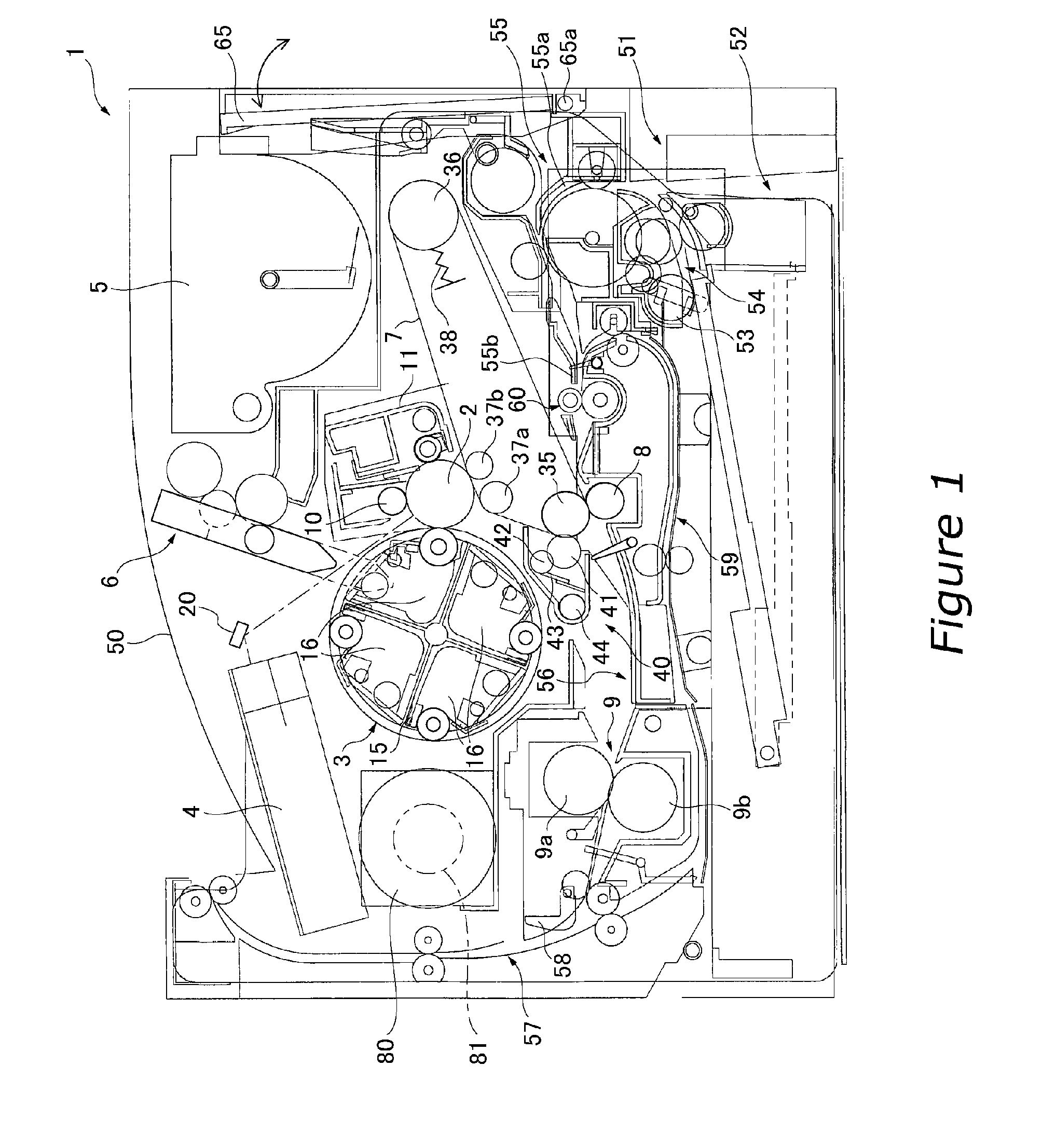
[0042]FIG. 1 shows a color printer 1 as a color image forming device according to an embodiment of the present invention. FIG. 1 is a view showing a frame format of the locations of each component, and thus the details of each portion are omitted.

[0043] Overall Structure

[0044] The color printer 1 is connected to a computer, for example, and is capable of printing a color image on a sheet (transfer medium) in accordance with image data sent from the computer. In this color printer 1, the right side of FIG. 1 is the side from which an operator operates the color printer 1. In the below description, the right side in FIG. 1 is referred to as the “front side” and the left side in FIG. 1 is referred to as the “rear side”.

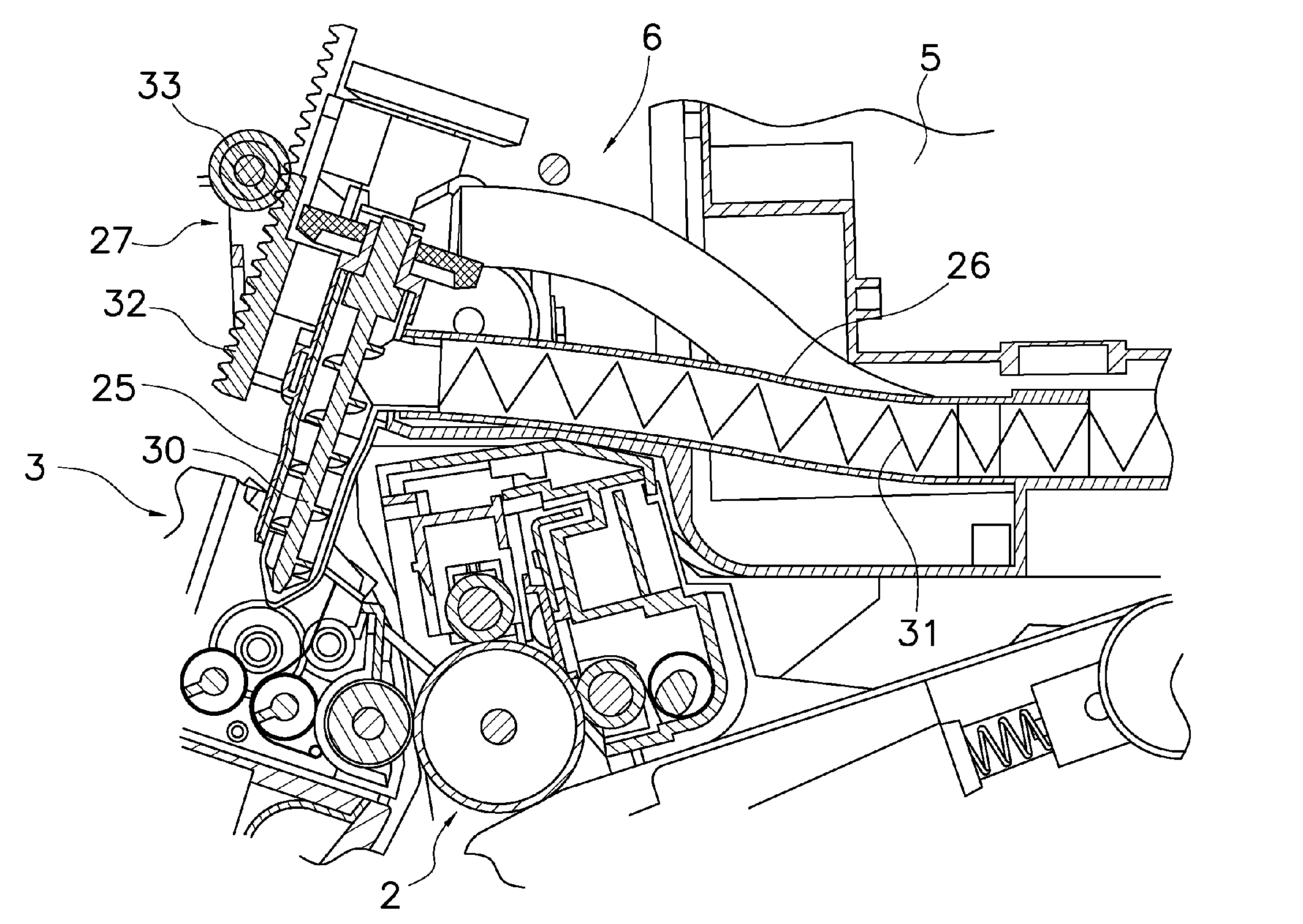
[0045] The color printer 1 includes a photosensitive drum 2, a rotary developing device 3, a laser unit 4, a toner container 5, a toner supply device 6, an intermediate transfer belt 7, a secondary transfer roller 8, and a fixing device 9.

[0046] Photosensitive Drum

[...


PUM


Abstract

An image forming device is disclosed, and includes a photosensitive drum, a laser unit for irradiating the photosensitive drum with laser light, developing units for developing the electrostatic latent image on the surface of the photosensitive drum, a toner container for containing toner to be supplied to the developing device, and toner supply pipes located so as to be movable between a supply position for supplying the developing units with the toner in the toner container, and a retracted position apart from the developing units. The toner supply pipes are located in a laser light path of the laser unit in the supply position, and are located so as to allow the laser light from the laser unit to reach the photosensitive drum in the retracted position.

Description

BACKGROUND OF THE INVENTION [0001] 1. Field of the Invention [0002] The present invention relates to a color image forming device, and more particularly to a color image forming device in which toner is supplied to a developing device from a toner container located apart from the developing device. [0003] 2. Background Information [0004] A color image forming device includes a plurality of developing units corresponding to a plurality of color toners. The developing units are arranged in several ways, such as in a lateral direction, around the photosensitive drum in a circumferential direction, and within a rotary frame located adjacent to the photosensitive drum. [0005] A rotary developing device having a plurality of the developing units within the rotary frame is shown in Japanese Unexamined Patent Publication No. 62-182768. In this device, the rotary frame is rotatably located adjacent to the photosensitive drum and supports four color developing units. When the rotary frame is ...

Claims


Application Information

Patent Timeline
Patent Type & Authority Applications(United States)
IPC IPC(8): G03G15/01G03G15/08
CPCG03G15/0121G03G2215/0177G03G2215/0685G03G15/0877G03G15/0879G03G15/0886G03G15/0875
Inventor TANDA, TETSUO
Owner KYOCERA DOCUMENT SOLUTIONS INC
Why Eureka
Try Eureka