Device, assembly, and system for reducing aerodynamic drag

a technology of aerodynamic drag and assembly, applied in the direction of roofs, mechanical equipment, transportation and packaging, etc., to achieve the effect of the air drag, boosting the drag reduction, and reducing the size of the flow separation zon

Active Publication Date: 2014-07-08
PRASKOVSKY ALEXANDER +2
View PDF59 Cites 29 Cited by
  • Summary
  • Abstract
  • Description
  • Claims
  • Application Information

AI Technical Summary

Benefits of technology

[0043]Accordingly, an object of the present invention is to provide a plurality of devices that can be attached to a vehicle or / and installed by the vehicle manufacturer in the appropriate locations and being able to reduce significantly aerodynamic drag of a vehicle.
[0132]With the above and other object in view there is also provided, in accordance with the invention, a sub-system that allows easy attachment to and removal from a vehicle any of the above-described devices, advantageously by a single person.

Problems solved by technology

Although the majority of efforts have been focused on reducing a vehicle drag for the cases of no wind or a head wind, a limited attention was also paid to reducing detrimental effects of side winds.
As such vehicle moves along its path, airflow around the vehicle produces the aerodynamic drag and increases the fuel consumption.
The magnitude of aerodynamic drag increases significantly with increasing vehicle speed.
All the above listed devices have several significant drawbacks that hinder their practical implementation.
The devices are large in size, heavyweight, inconvenient in use and may interfere with operating cargo vehicles like loading and unloading.
The most significant drawback of those devices is their inefficiency at side winds.
Prior art SSVG for motor vehicles share a significant drawback that was established in numerous scientific studies, namely, low efficiency in reducing air drag.
The low efficiency results from considerable differences in operational requirements for vehicles from those for airfoils, combustion chambers, automotive engines and other conventional applications of SSVG.
Such self-adaptation of airflow ensures the lowest aerodynamic resistance of the open-type SSVG in accordance with the major requirement for conventional applications although leads to the low intensity and lifespan of generated small-scale vortices.
At the same time, own aerodynamic resistance of SSVG is of low significance for motor vehicles due to a low driving speed of typically below 130 km / h and a very high air drag in the drag-producing volumes on bluff edges of large tractors and trailers.
Being the open-type devices with low aerodynamic resistance, they are physically inappropriate for producing intensive small-scale vortices with sufficiently large lifespan.
Therefore, existing devices for reducing aerodynamic drag for vehicles at a cruise speed have the following significant shortcomings that hinder their practical implementation:The devices are unable to reduce aerodynamic drag of vehicles to any significant degree, andthe majority of the devices are designed for airflow along the travel direction and they have a low efficiency in reducing detrimental effects of side winds.
Additional shortcomings of existing devices for reducing an air drag and mitigating detrimental effects of side winds for long distance cargo vehicles at typical highway speeds are as follows.The devices may interfere with loading and unloading cargo vehicles including opening and closing the trailer doors and backing into loading docks.The devices may extend significantly from the trailer surfaces and be easily damaged when a vehicle maneuvers on uneven roadsides and / or is backed into loading docks.The devices are technologically complicated, inconvenient to use and non-durable.The devices that are permanently mounted on a trailer do not address an issue of separate ownership, for example, a tractor may belong to an independent owners-operator and towed trailers may belong to a fleet-owning company.Existing mounting systems for attaching / detaching items such as tarp, temporary signs and the like to external vehicle surfaces do not allow attaching / detaching the items to trailer roof and sides by one person.

Method used


Image

  • Device, assembly, and system for reducing aerodynamic drag
  • Device, assembly, and system for reducing aerodynamic drag
  • Device, assembly, and system for reducing aerodynamic drag

Examples


Embodiment Construction

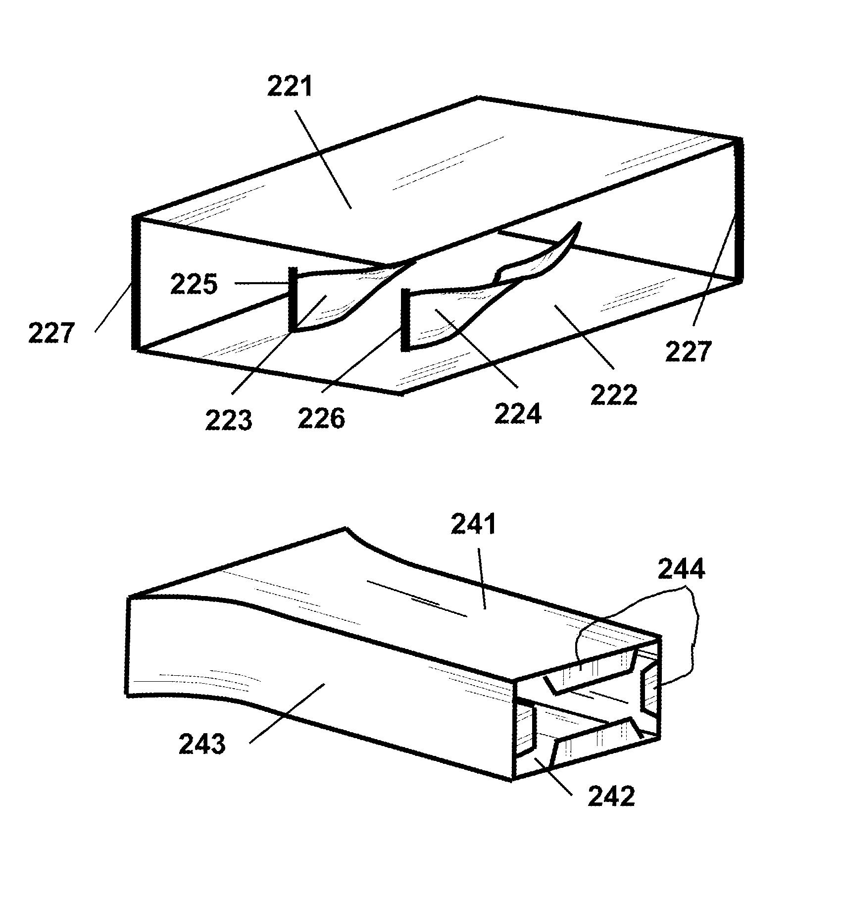
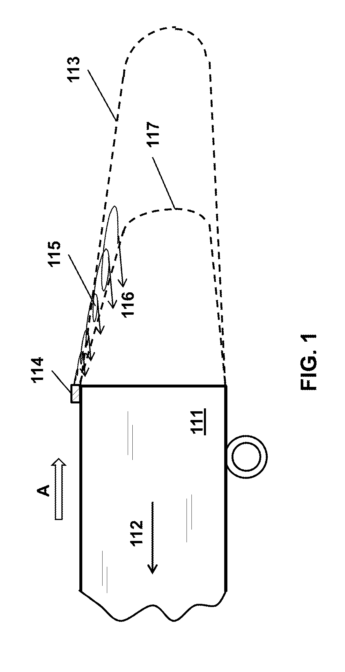
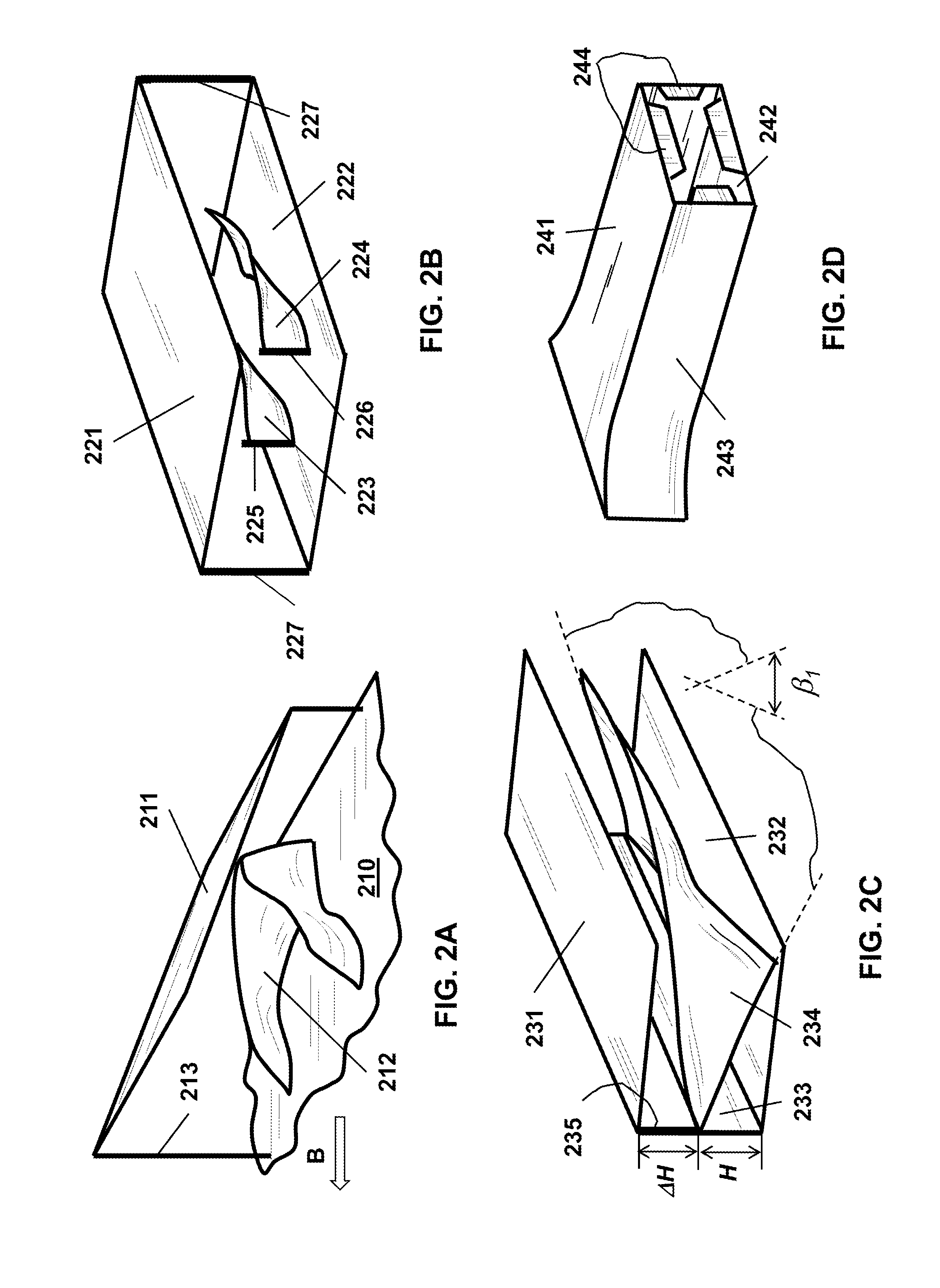
[0150]Referring now to the figures of the drawing in detail, there are seen various illustrations of basic conceptual embodiments of the invention. While specific implementations are described, it should be understood that this is done for illustration purposes only. The described small-scale vortex generators (SSVG) and their components may be modified and a plurality of other elements for efficient generation of small-scale vortices may be incorporated into the generators individually or in any combination. The described new fairing devices, sub-systems for reducing air drag and mitigating detrimental effects of side wind, sub-system for attaching / detaching devices to motor vehicles and their components may be modified and a plurality of other means for performing the designated functions may be incorporated into the devices and sub-system individually or in any combination. Those and other modifications may be incorporated into the SSVG, fairing devices and the sub-systems withou...


PUM


Abstract

A system and methods for reducing aerodynamic drag and mitigating detrimental side wind effects on vehicles moving through air or water with a plurality of new subsystems disposed in a plurality of locations on the vehicles. Each one of the subsystems includes a sub-set of small-scale vortex generators that have an intake for air from airflow around the vehicle and that produce intensive small-scale vortices with large lifespan, and / or a new fairing device that streamlines airflow and produces a sheet of small-scale-vortices. The subsystems direct the vortices with large lifespan and / or sheets of vortices into the vehicle's drag-producing volumes. The vortex generators have one or several air channels preventing airflow from bypassing vortex-producing elements and the elements inside the channels that produce small-scale vortices. The novel fairing devices are of bluff shape and / or with bluff obstructions and / or slots for generating sheets of intensive small-scale vortices in surrounding airflow.

Description

CROSS-REFERENCE TO RELATED APPLICATION[0001]This application claims the benefit under 35 U.S.C. §119(e) of provisional patent application No. 61 / 553,178, filed Oct. 29, 2011 and of provisional patent application No. 61 / 694,825, filed Aug. 30, 2012; the prior applications are herewith incorporated by reference.BACKGROUND OF THE INVENTION[0002]1. Field of the Invention[0003]The invention relates to a method, to a device, and to an assembly or system for reducing aerodynamic drag and mitigating detrimental effects of side wind on vehicles moving through air or water including but not limited to heavy cargo trucks, cargo containers, liquid cargo cisterns, buses, RV's, SUV's, vans, passenger cars, railroad cars, helicopters, airplanes, aerostats, ships and submarines, and, more specifically, to systems for introducing intensive small-scale turbulent vortices with large lifespan and / or sheets of small-scale-vortices into the vehicle's drag producing volumes. The invention also relates to ...

Claims


Application Information

Patent Timeline
Patent Type & Authority Patents(United States)
IPC IPC(8): B62D35/00F15D1/10
CPCB62D35/001F15D1/10Y10T137/85938
Inventor PRASKOVSKY, ALEXANDERPRASKOVSKAYA, ELEANORPRASKOVSKY, ANDREW
Owner PRASKOVSKY ALEXANDER
Why Eureka
Try Eureka