Crown molding scales for a miter saw

a technology of miter saw and scale, which is applied in the direction of metal sawing accessories, mechanical measuring arrangements, instruments, etc., can solve the problems of crown molding installation that is difficult and tedious for professionals and “do-it-yourselfers”, the miter joint will not fit properly, and the compound angle cut is incorrect, so as to eliminate the need for crown molding and reduce errors. , the effect of quick material placemen

Inactive Publication Date: 2014-07-15
GLOMB SR TIMOTHY J
View PDF12 Cites 3 Cited by
  • Summary
  • Abstract
  • Description
  • Claims
  • Application Information

AI Technical Summary

Benefits of technology

[0012]1. The objective of the invention is to provide the means to quickly locate and place material on the accurate location of the miter saw table. The Crown Molding Scales are comprised of a series of dimensional scales on the table of a miter saw. There are scales to provide dimensions on the saw table relative to the saw fence and there are scales to provide dimensions relative to the saw blade at a multitude of angles. The scales are fixed and do not move on the table. The Crown Molding Scales eliminate the need for and reduce errors caused by hand held tape measures or rulers used to locate the correct dimension on the miter saw table. They are beneficial for cutting crown molding, measuring items, and will assist in cutting any material the saw manufacturer recommends. The scales could be placed on or in a new saw during production by a manufacturer. Or the scales could be placed on or in a material to be placed on a new or old saw.

Problems solved by technology

In the art of finish carpentry, specifically moldings and decorative trim work, it is commonly understood that installing crown molding is a difficult and tedious task for professionals and “do-it-yourselfers”.
Frequently, a miter joint will not fit properly after the molding is cut.
Generally, the compound angle cut is incorrect and the molding piece may not be able to be adjusted or re-cut for use.
6. Frequently, a correct coped cut will not fit properly against the first piece of molding.
This is common in the art and generally is due to the imperfections with room construction or the molding, or installer error.
Through trial and error the installer eventually gets it to fit, but at the cost of additional labor time and expense and replacement material costs.

Method used


Image

  • Crown molding scales for a miter saw
  • Crown molding scales for a miter saw
  • Crown molding scales for a miter saw

Examples


Embodiment Construction

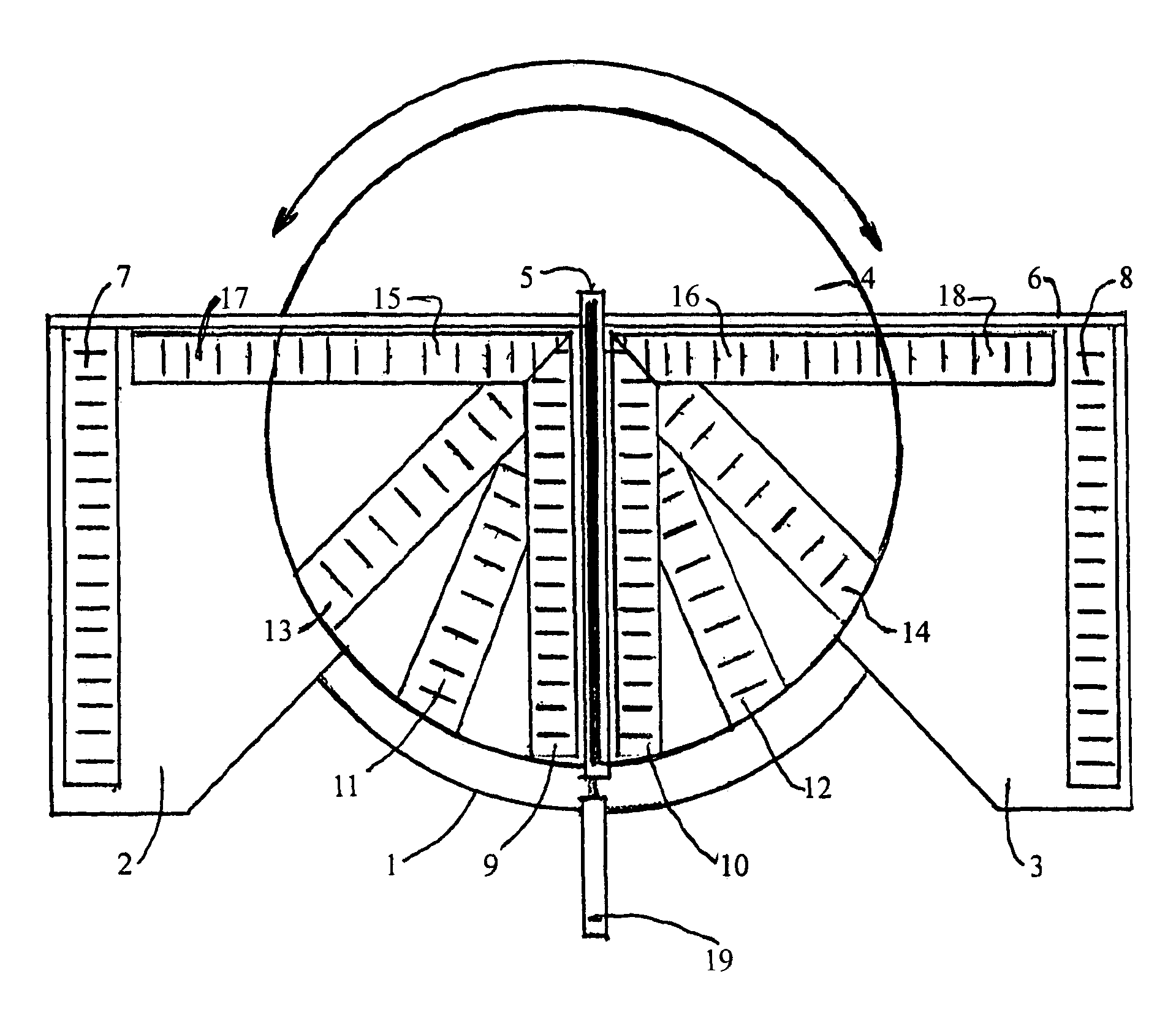
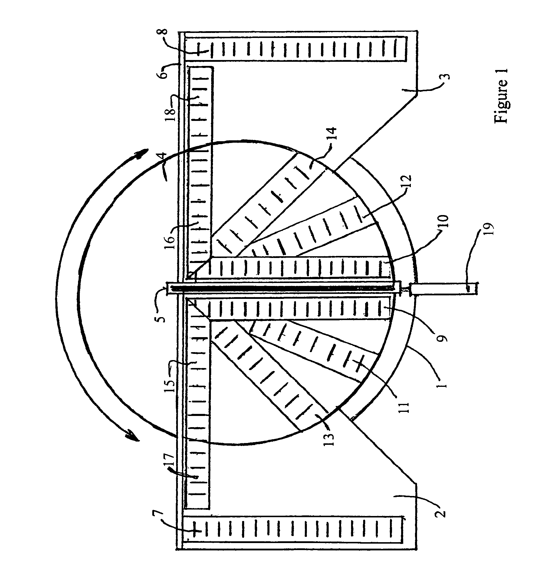
[0038]1. This invention is comprised of a series of dimensional scales (linear measuring devices) on a miter saw table, each scale having markings for measuring along a length thereof. This invention will provide the means to allow an installer to quickly locate and accurately place material on the desired location of a miter saw table. In FIG. 1, the front edge 1 of the miter saw table is for location only. Reference to a saw table would mean the tables of a miter saw and would include both the fixed portions 2 and 3 and the rotating portion 4 of a miter saw table. Reference of the scales would include scales 7, 8, 9, 10, 11, 12, 13, 14, 15, 16, 17 and 18. Scales 7, 8, 17 and 18 are on the fixed portions 2 and 3 respectively of a saw table. Scales 7 and 8 provide dimensions relative to the miter saw fence 6. Scales 9, 10, 11, 12, 13, 14, 15 and 16 are on the rotating portion 4 of a saw table. Scales 9, 10, 11, 12, 13, 14, 15 and 16 provide dimensions relative to the saw fence 6 and...


PUM

PropertyMeasurementUnit
90 degree angleaaaaaaaaaa
lengthaaaaaaaaaa
angleaaaaaaaaaa

Abstract

The invention is includes a series of dimensional scales (linear measuring device) on the top surface of a miter saw table. The scales allow for measurements to be located or obtained on the saw table relative to the saw fence and relative to the saw blade. The scales may replace the need for a hand held tape measure or ruler for measuring or marking the saw table surface when cutting crown molding or other materials. The scales could be placed on or in a saw during production by a manufacturer. The scales could be placed on or in a material to be placed on a saw during production by a manufacturer. The scales could be placed on or in a material to be placed on an existing saw.

Description

CROSS-REFERENCE TO RELATED APPLICATIONS[0001]This application claims benefits of Provisional Application for Patent No. 61 / 276 / 835, filed Sep. 18, 2009, applicant—Timothy J. Glomb Sr., Kennett Square, Pa.STATEMENT REGARDING FEDERALLY SPONSORED RESEARCH OR DEVELOPMENT[0002]“Not Applicable”REFERENCE TO A SEQUENCE LISTING, A TABLE, OR A COMPUTER PROGRAM, LISTING COMPACT DISC APPENDIX[0003]“Not Applicable”BACKGROUND OF THE INVENTION[0004]1. The invention pertains to an improvement to a miter saw table for locating dimensions on the table. In the art of finish carpentry, specifically moldings and decorative trim work, it is commonly understood that installing crown molding is a difficult and tedious task for professionals and “do-it-yourselfers”. Crown molding is a decorative trim generally seen in a room along the top of the walls where the wall meets the ceiling. The bottom edge of the molding lies against the wall, the top edge of the molding lies against the ceiling and the face of t...

Claims


Application Information

Patent Timeline
Patent Type & Authority Patents(United States)
IPC IPC(8): B23D45/14B27B5/29B23D47/04B23Q17/22B26D7/01B27G5/02
CPCB23D47/025B23D59/002Y10T83/849Y10T83/762Y10T83/858Y10T83/857Y10T83/7697Y10T83/76
Inventor GLOMB, SR., TIMOTHY, J.
Owner GLOMB SR TIMOTHY J
Why Eureka
Try Eureka