Wireless energy transfer with anisotropic metamaterials

a metamaterial and anisotropic technology, applied in the direction of inductance, inductance, elevator, etc., can solve the problem of high ineffective induction method, and achieve the effect of enhancing coupling

Active Publication Date: 2014-07-22
MITSUBISHI ELECTRIC RES LAB INC
View PDF40 Cites 8 Cited by
  • Summary
  • Abstract
  • Description
  • Claims
  • Application Information

AI Technical Summary

Problems solved by technology

To optimize the energy, a distance between the source and the sink should be as small as possible, because over greater distances the induction method is highly ineffective.
It is a challenge to enhance the coupling.

Method used


Image

  • Wireless energy transfer with anisotropic metamaterials
  • Wireless energy transfer with anisotropic metamaterials
  • Wireless energy transfer with anisotropic metamaterials

Examples


Embodiment Construction

[0029]Embodiments of the invention are based on a realization that a metamaterial, e.g., a negative index material (NIM) and / or single-negative (SNG) metamaterial, isotropic and anisotropic metamaterials, arranged in an electromagnetic (EM) near-field on a path of an evanescent wave while energy is transferred wirelessly, increases amplitude of the evanescent wave and, thus, optimizes the efficiency of the energy transfer.

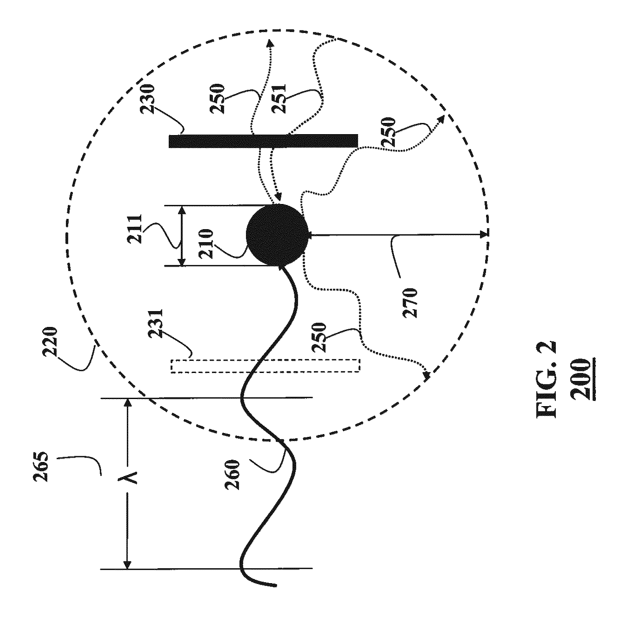
[0030]FIG. 2 shows a system 200 according an embodiment of the invention. The system is configured to exchange, e.g., transmit or receive, energy wirelessly and includes an electromagnetic (EM) non-radiative structure 210 having dimensions 211, e.g., a diameter, configured to generate an electromagnetic near-field 220 when the energy is received by the structure and exchange the energy wirelessly via a coupling of evanescent waves.

[0031]Most of the energy is reactive and confined in the transmitter or resonator and only a small portion of the energy can radiate to ...


PUM


Abstract

A system includes a structure configured to exchange the energy wirelessly via a coupling of evanescent waves and an anisotropic metamaterial arranged within an electromagnetic near-field such that an amplitude of the evanescent waves is increased. The structure is electromagnetic and non-radiative, wherein the structure generates the electromagnetic near-field in response to receiving the energy.

Description

RELATED APPLICATIONS[0001]This application is a continuation in part of U.S. patent application Ser. No. 12 / 731,544 entitled “Wireless Energy Transfer with Metamaterials,” filed by Bingnan Wang et al. on Mar. 25, 2010, claimed priority from, and incorporated herein by reference.FIELD OF THE INVENTION[0002]The present invention relates to transferring energy, and more particularly, to transferring energy wirelessly.BACKGROUND OF THE INVENTION[0003]Wireless Energy Transfer[0004]Inductive coupling is used in a number of wireless energy transfer applications such as charging a cordless electronic toothbrush or hybrid vehicle batteries. In coupled inductors, such as transformers, a source, e.g., primary coil, generates energy as an electromagnetic field, and a sink, e.g., a secondary coil, subtends that field such that the energy passing through the sink is optimized, e.g., is as similar as possible to the energy of the source. To optimize the energy, a distance between the source and th...

Claims


Application Information

Patent Timeline
Patent Type & Authority Patents(United States)
IPC IPC(8): H04B5/00
CPCH04B5/00H04B5/0037H04B5/0081B66B7/00
Inventor WANG, BINGNANTEO, KOON HOOYERAZUNIS, WILLIAM
Owner MITSUBISHI ELECTRIC RES LAB INC
Why Eureka
Try Eureka