Energy transfer systems and methods for mobile vehicles

a technology of energy transfer and mobile vehicles, applied in the field of energy transfer systems and methods for mobile vehicles, can solve the problems of limiting the usefulness of electric vehicles traveling over longer distances, not having enough parking areas, and requiring two if not more hours to recharge the power source of electric vehicles, so as to save space and cos

Inactive Publication Date: 2011-07-28
TOYOTA JIDOSHA KK
View PDF3 Cites 334 Cited by
  • Summary
  • Abstract
  • Description
  • Claims
  • Application Information

AI Technical Summary

Benefits of technology

[0011]Note that in the above system, the transmitter array is described as being located in the roadway and the receiver is located in the vehicle. Other embodiments may include a transmitter array in the vehicle and the receiving array in the roadway. It also possible that the roadway and vehicle includes both a transmitter array and receiver array permitting energy transfer in either direction under the control of the energy transfer controller. Certain transmit and receive components such as inductive coils may be used for bidirectional transmit and receive operations in the vehicle and in the roadway to save space as well as cost. The bidirectional transfer of energy may be used to routinely supply electric energy to the vehicle, and occasionally to provide energy from the vehicle to the roadway.

Problems solved by technology

While this solves problems like pollution in particular, carbon emissions, it creates other new problems.
One such challenge is filling or charging an energy source such as a battery for later use.
One particular problem is that to recharge the power source of an electric vehicle often requires two if not more hours.
However, for most existing service stations do not have enough parking areas for the vehicles while they are being recharged.
While this is acceptable for vehicles that are used only for commuting, this limits their usefulness when traveling over longer distances.
This often limits the usefulness of fully electric vehicles to less than 100 miles.
There have been attempts to transfer energy to vehicles while they are moving, but such efforts have not been effective.
Once particular, problem is that vehicles travel quickly over transfer coils.
High vehicle speeds result in small values for transfer times. This has prevented existing system to effectively transfer energy to moving vehicles.
Furthermore, while there have also been attempts to create energy transfer centers that employ methods that work well for stationary objects, a moving object cannot be recharged by such methods.

Method used


Image

  • Energy transfer systems and methods for mobile vehicles
  • Energy transfer systems and methods for mobile vehicles
  • Energy transfer systems and methods for mobile vehicles

Examples


first embodiment

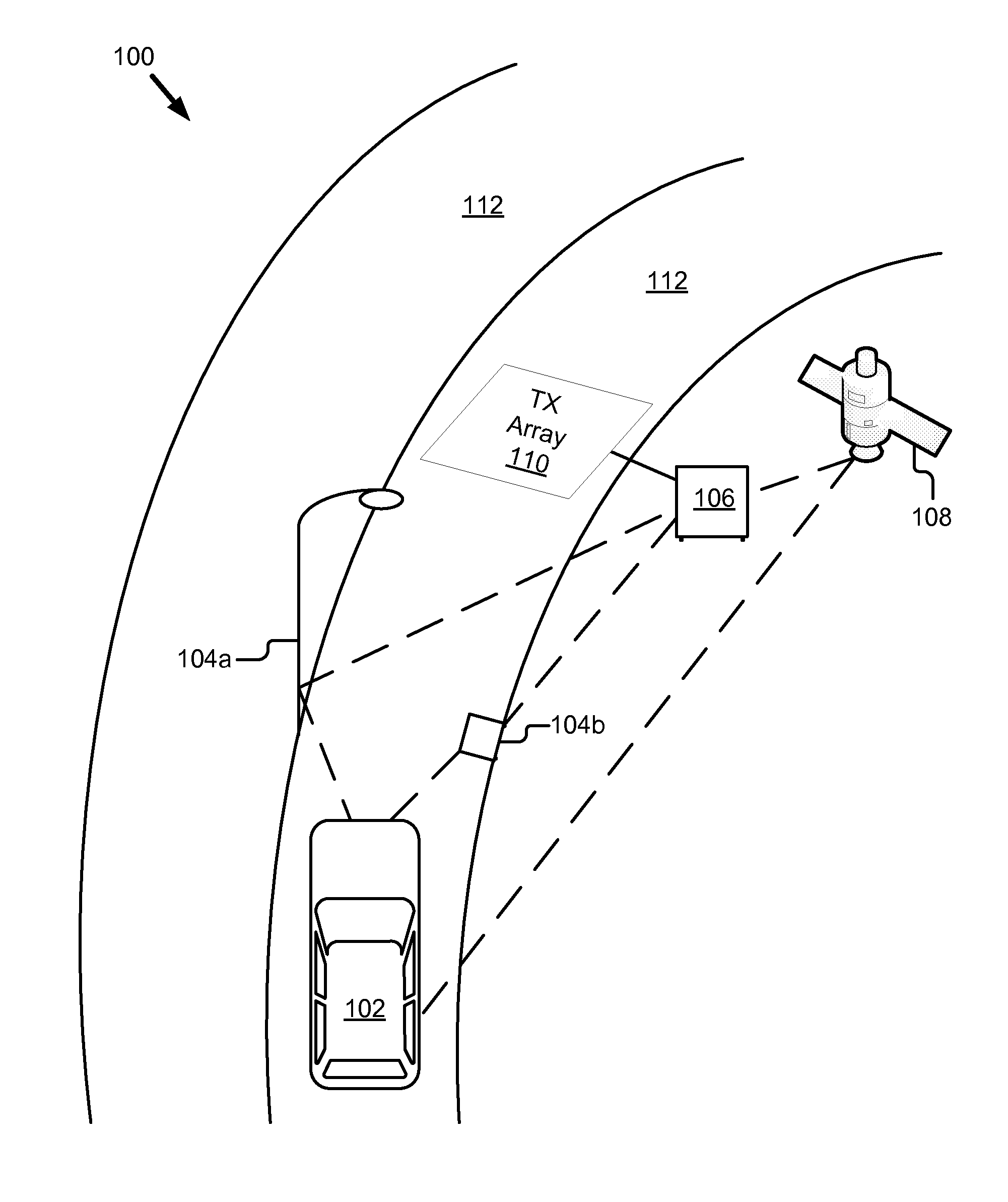
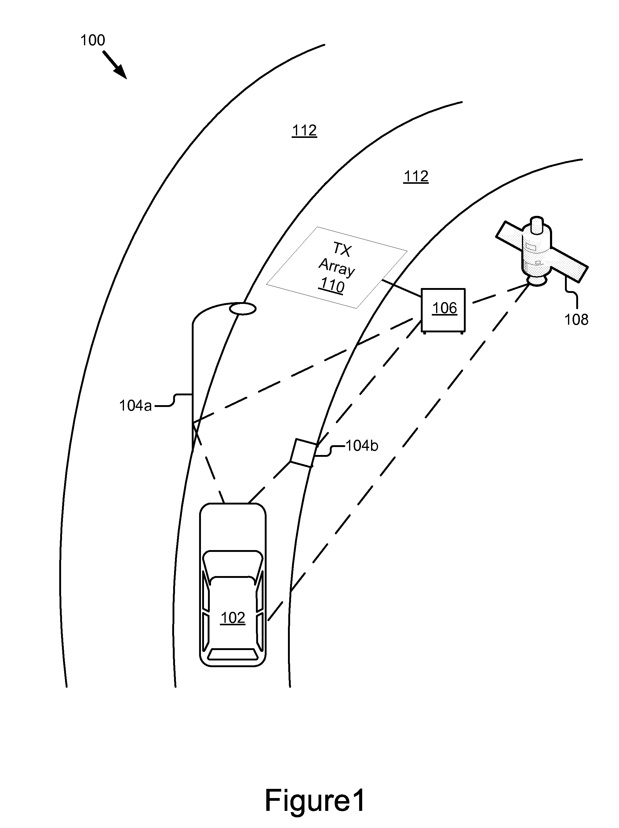
[0038]Referring now to FIG. 1, an energy transfer system 100 is shown. The energy transfer system 100 includes a mobile vehicle 102, one or more location sensors 104a, 104b, an energy transfer controller 106, optionally a global positioning system 108 and a transmitter array 110. In this embodiment, consistent with the principles of the present invention, an energy transfer system 100 is located along a curved road way 112. The energy transfer system 100 is preferably deployed at locations where the mobile vehicle 102 has reduced speed. In particular, the reduced speed of the mobile vehicle 102 translates into a greater transfer time which means more energy transferred per coil and fewer coils required transfers per mile.

[0039]The mobile vehicle 102 is any type of vehicle that requires electrical power. The mobile vehicle 102 includes various other electrical, mechanical and communications systems available on various hybrid and fully electric vehicles such as the Prius automobile m...

second embodiment

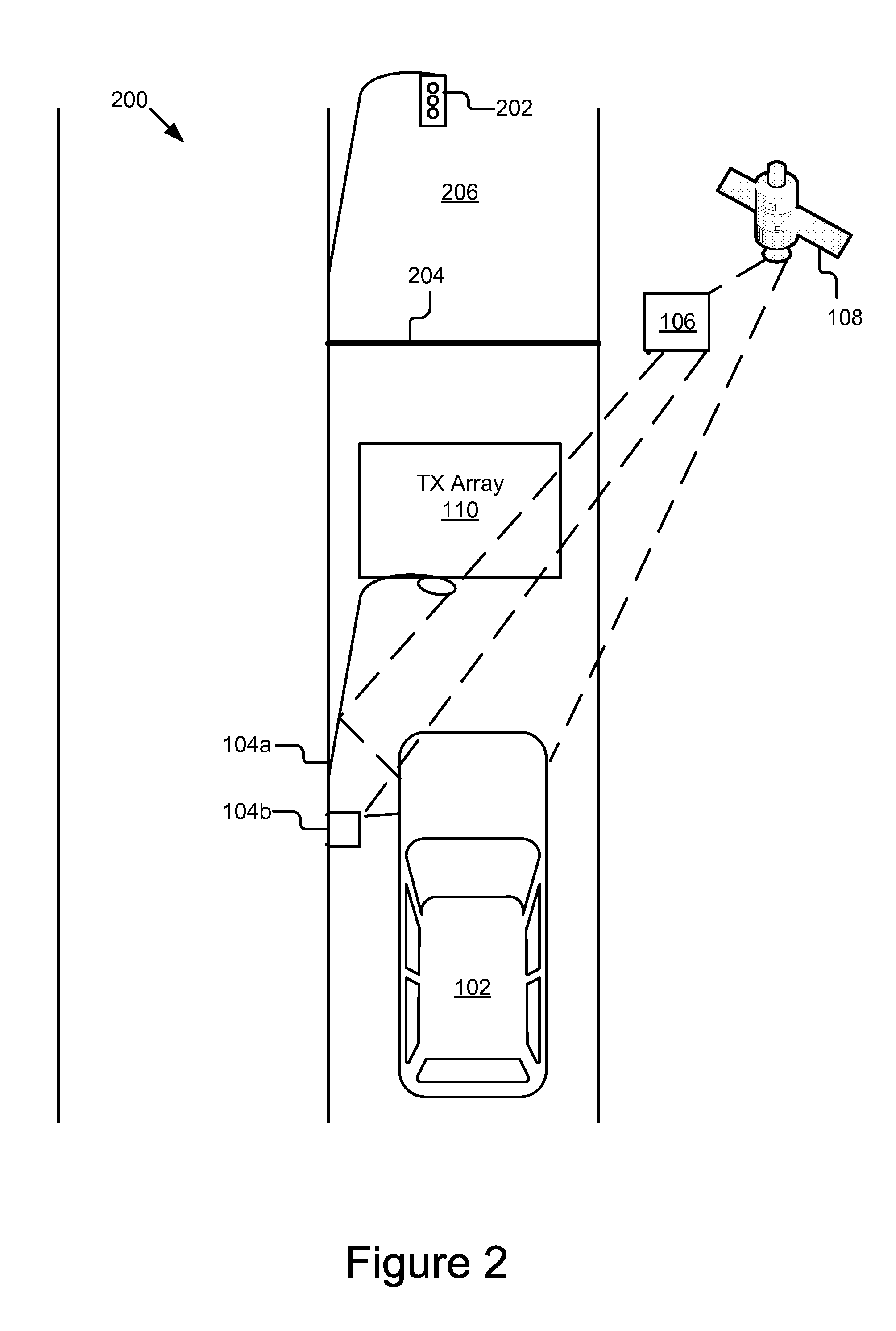
[0044]Referring now to FIG. 2, the energy transfer system 200 is shown. This embodiment of the energy transfer system 200 includes the mobile vehicle 102, one or more location sensors 104a, 104b, an energy transfer controller 106, optionally a global positioning system 108 and the transmitter array 110. Like reference numerals have been used to represent components of the system 200 with the same or similar functionality as system 100.

[0045]In this embodiment, consistent with the principles of the present invention, the energy transfer system 200 is located just before a traffic light 202. A stop line 204 corresponding to the stop light 202 indicates where a vehicle moving past the traffic light 202 should stop. In accordance with the present invention, the transmitter array 110 is positioned in the roadway 206, beneath the surface and a predetermined distance before the stop line 204. For example, the transmitter array 110 is positioned a distance of between ten to fifty feet befor...


PUM


Abstract

An energy transfer system comprises a transmitter array, an energy transfer controller, a receiver array, a charging module. The transmitter array is embedded in a roadway and the energy transfer controller is coupled to the transmitter array. The receiver array and the charging module are part of a mobile vehicle. The transmitter array and the receiver array each include a plurality of coils. The energy transfer controller estimates a likely trajectory of the mobile vehicle and energizes individual coils of the transmitter array using this position estimate. The energy transfer controller varies the resonant circuit component values of the transmitter during the transfer cycle such as resonant coupling capacitance values. The charging module also varies the resonant circuit component values of the coils in the receiver array to match the transfer array for transfer of energy from the transmitter array to the receiver array. The present invention also includes a method for energy transfer.

Description

BACKGROUND OF THE INVENTION[0001]1. Field of the Invention[0002]This invention relates to systems and methods for transferring energy. In particular, the present invention relates to system and method for transferring energy from a roadway to a moving vehicle.[0003]The terms roadway and vehicle are taken broadly. Alternatively, the two components may be a pathway and a moving electricity-powered system. The invention may be used as part of a smaller system designed for indoor use where the roadway or path may be called a floor or a raceway and the vehicle may be a cart or a scooter or forklift truck.[0004]2. Description of the Background Art[0005]As fossil fuel becomes a remnant of the past, alternative energy sources usher in a new era of harnessing, storing and utilizing energy. In particular in the context of motor vehicles, engines once driven by the burning of gasoline are being replaced with engines that run on electricity stored in batteries in the vehicle. While this solves ...

Claims


Application Information

Patent Timeline
Patent Type & Authority Applications(United States)
IPC IPC(8): H02J7/02G06F1/26G06F7/04G01C21/26G06Q30/00
CPCB60L5/005B60L11/182B60L11/1831B60M7/003G06Q30/04Y02T90/121Y02T90/12Y02T90/122Y02T90/125Y02T90/14Y02T10/7005B60L53/122B60L53/126B60L53/39Y02T10/70Y02T10/7072
Inventor MELEN, ROGER D
Owner TOYOTA JIDOSHA KK
Why Eureka
Try Eureka