Runtime compensated oscillator

a technology of oscillator and runtime, applied in the field of oscillators, can solve problems such as the delay of propagation of comparator devices, and achieve the effect of reducing the delay of propagation

Active Publication Date: 2014-07-22
INFINEON TECH AUSTRIA AG
View PDF7 Cites 6 Cited by
  • Summary
  • Abstract
  • Description
  • Claims
  • Application Information

AI Technical Summary

Problems solved by technology

Comparators, however, have a propagation delay that is dependent on a plurality of different factors and that influence the frequency of the oscillating signal.

Method used


Image

  • Runtime compensated oscillator
  • Runtime compensated oscillator
  • Runtime compensated oscillator

Examples


Embodiment Construction

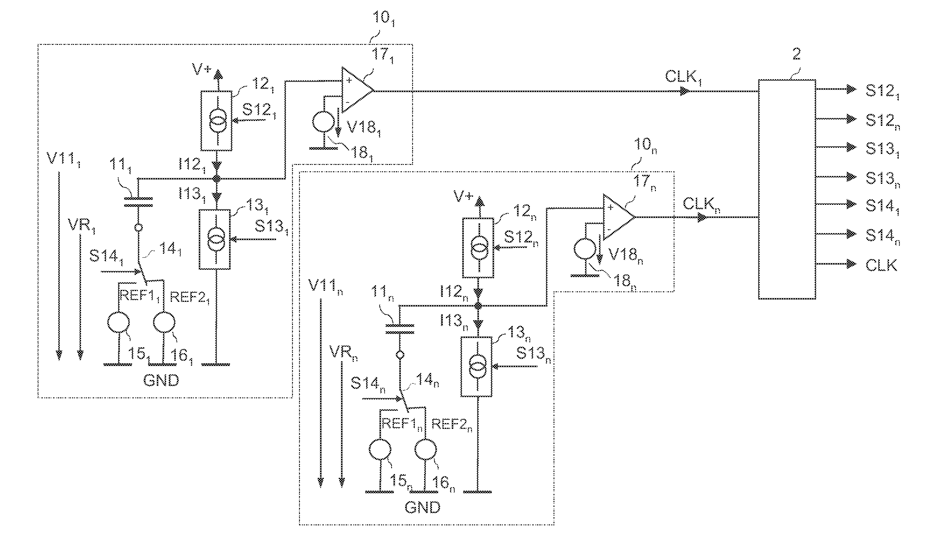
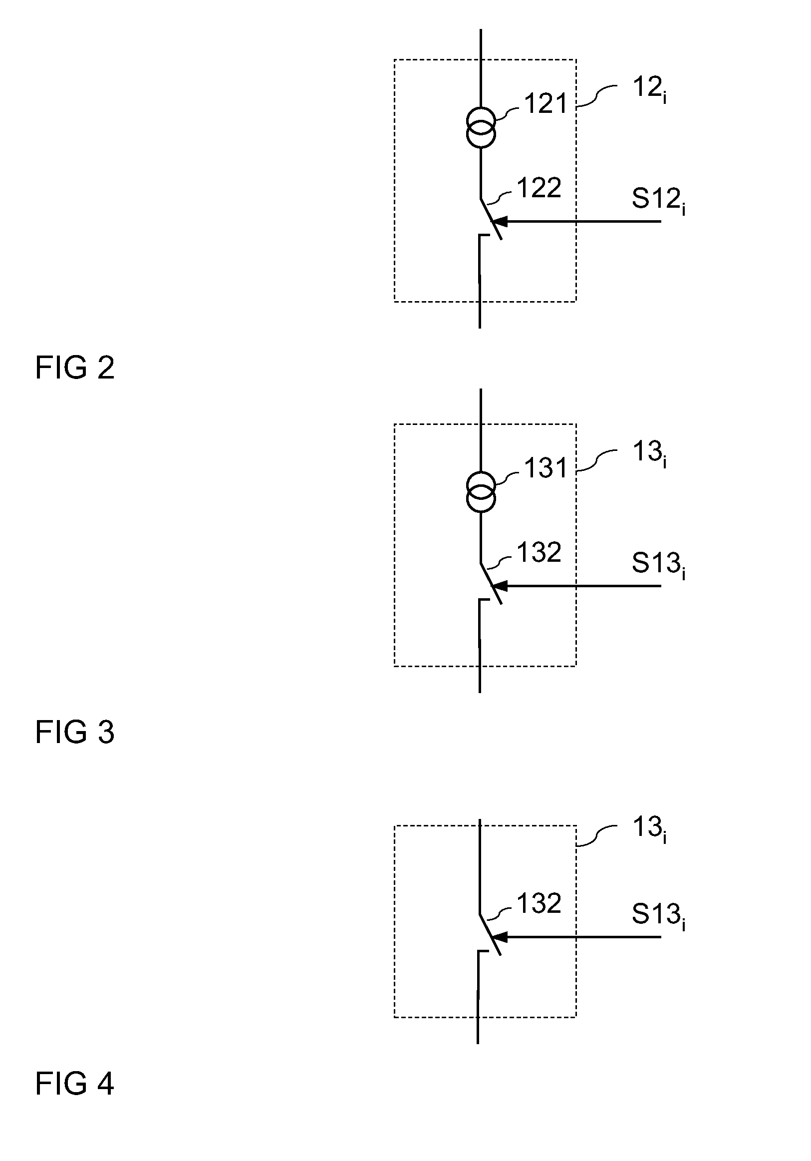
[0022]FIG. 1 illustrates a first embodiment of an oscillator circuit. The oscillator circuit includes a plurality of n, with n≧2, capacitive storage elements 111, 11n, such as, for example, capacitors. The oscillator circuit of FIG. 1 includes n=2 capacitive storage elements. However, this is only an example. It is also possible to provide more than n=2 capacitive storage elements, which will be explained in further detail with reference to FIG. 10 herein below. The capacitive storage elements are, in particular, implemented such that they have a linear capacitance, which means that the voltage across each capacitive storage element increases linearly, when the charge stored in the capacitive storage element increases linearly. The capacitive charge storage elements can be implemented as conventional capacitors, such as plate capacitors, as a coupling capacitance between lines, or as a MOS capacitor.

[0023]Each of the capacitive storage elements 111, 11n is included in an oscillator ...


PUM


Abstract

Disclosed is a method for generating an oscillating signal and an oscillator circuit.

Description

TECHNICAL FIELD[0001]Embodiments of the present invention relate to an oscillator and to a method for generating an oscillating signal.BACKGROUND[0002]Oscillators are widely used in electronic circuits for generating a clock signal. Those clock signals are, for example, used in switching converters for defining the frequency of a pulsewidth modulated (PWM) signal, in digital circuits for synchronizing the operation of individual devices in the digital circuit, or in communication devices for synchronizing a transmitter and a receiver each coupled to a transmission channel.[0003]Different types of oscillators are known, such as quartz oscillators, micromechanical oscillators, or relaxation oscillators. Relaxation oscillators include a capacitive component that is periodically charged and discharged with a constant current in order to generate a triangular oscillating signal. In this kind of oscillator, a voltage across the capacitive component is compared with at least one reference ...

Claims


Application Information

Patent Timeline
Patent Type & Authority Patents(United States)
IPC IPC(8): H03K3/26
CPCH03K3/011H03K4/502H03K3/36H03K4/50
Inventor FELDTKELLER, MARTIN
Owner INFINEON TECH AUSTRIA AG
Why Eureka
Try Eureka