Particle beam therapy system

a beam therapy and particle technology, applied in the field of particle beam therapy system, can solve the problems of low cost of system using any one of the methods described in japanese patent no. 2596292 and jp-a-2005-332794, and the leakage of extracted beams with a relatively large irradiation dose in an area present, and achieve the effect of low cost, low cost and low cos

Active Publication Date: 2010-08-10
HITACHI LTD
View PDF15 Cites 145 Cited by
  • Summary
  • Abstract
  • Description
  • Claims
  • Application Information

AI Technical Summary

Benefits of technology

[0012]In a method described in Non-Patent Document 1, a delayed irradiation dose of a beam irradiated immediately after the turning-off can be reduced. However, after that, the extracted beam with a small irradiation dose may leak in an area present between irradiation spots. Especially, the extracted beam with a relatively large irradiation dose may leak in an area present between irradiation spots during the change in the amount of the exciting current flowing in the scanning magnet in the remote spot irradiation method in which the irradiation spots are remotely located and are to be irradiated. In addition, the radio frequency acceleration voltage is turned off for a long time during movement of a beam spot from an irradiation spot to another irradiation spot in the remote spot irradiation method. The beam circulating in the synchrotron therefore becomes unstable. This results in a reduction in the quality of the irradiation beam.
[0022]In addition, according to the present invention, the particle beam therapy system is capable of providing a therapy for a remote irradiation spot with an improved irradiation beam in a remote spot irradiation method in which an irradiation spot is remotely located and is to be irradiated. The particle beam therapy system can be realized at low cost and is capable of achieving an irradiation beam suitable for a particle beam therapy using a spot scanning method.

Problems solved by technology

As a result, a system using any one of the methods described in Japanese Patent No. 2596292 and JP-A-2005-332794 is expensive.
However, after that, the extracted beam with a small irradiation dose may leak in an area present between irradiation spots.
Especially, the extracted beam with a relatively large irradiation dose may leak in an area present between irradiation spots during the change in the amount of the exciting current flowing in the scanning magnet in the remote spot irradiation method in which the irradiation spots are remotely located and are to be irradiated.
In addition, the radio frequency acceleration voltage is turned off for a long time during movement of a beam spot from an irradiation spot to another irradiation spot in the remote spot irradiation method.
The beam circulating in the synchrotron therefore becomes unstable.
This results in a reduction in the quality of the irradiation beam.

Method used


Image

  • Particle beam therapy system
  • Particle beam therapy system
  • Particle beam therapy system

Examples


first embodiment

[0030]A description will be made of the configuration and operations of a particle beam therapy system according to the present invention with reference to FIGS. 1 to 5F.

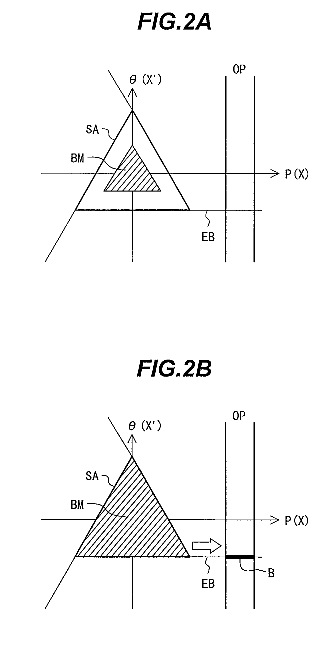
[0031]First, a description will be made of the entire configuration of the particle beam therapy system according to the first embodiment and the principle of irradiation of a particle beam with reference to FIGS. 1 to 3B.

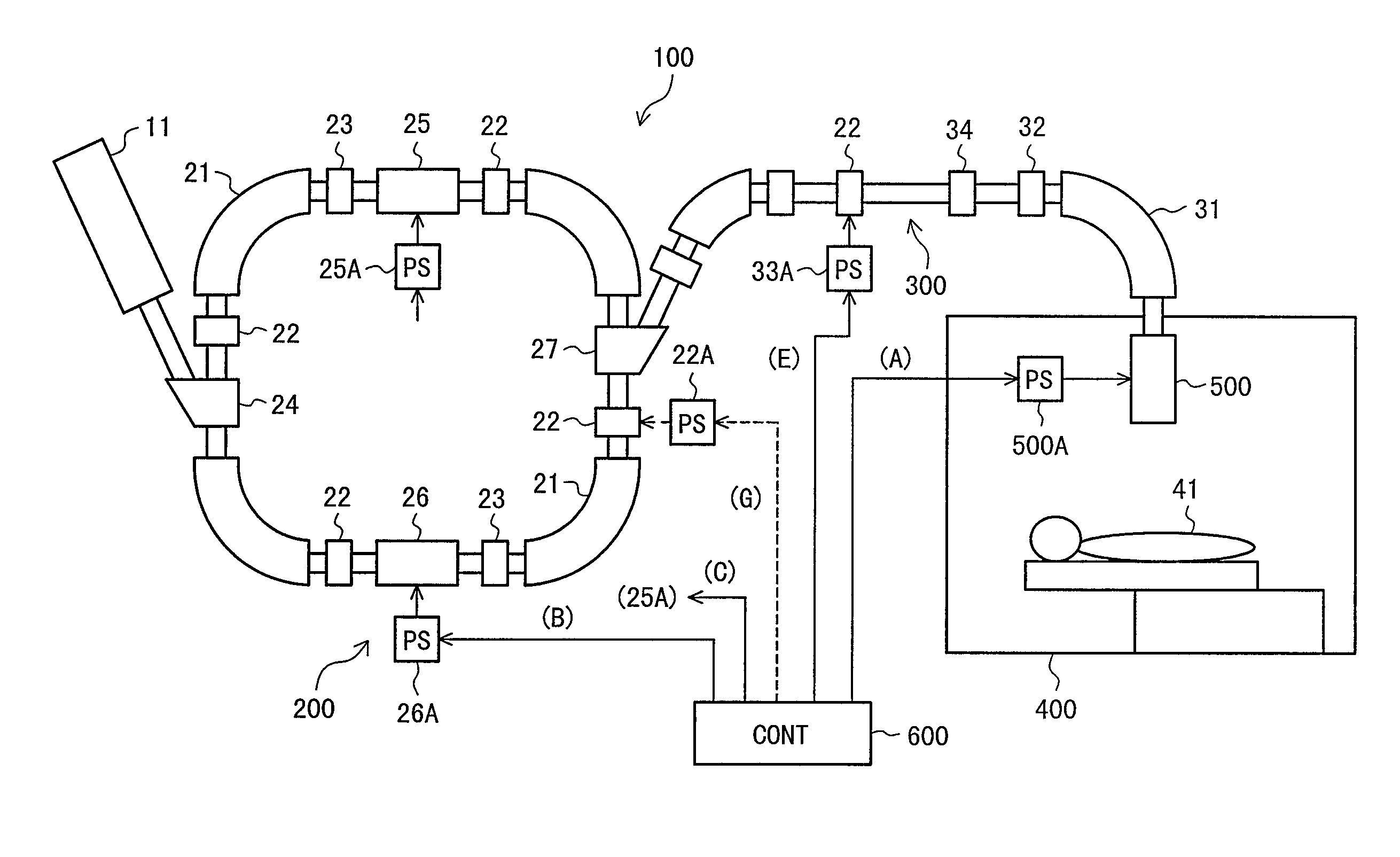
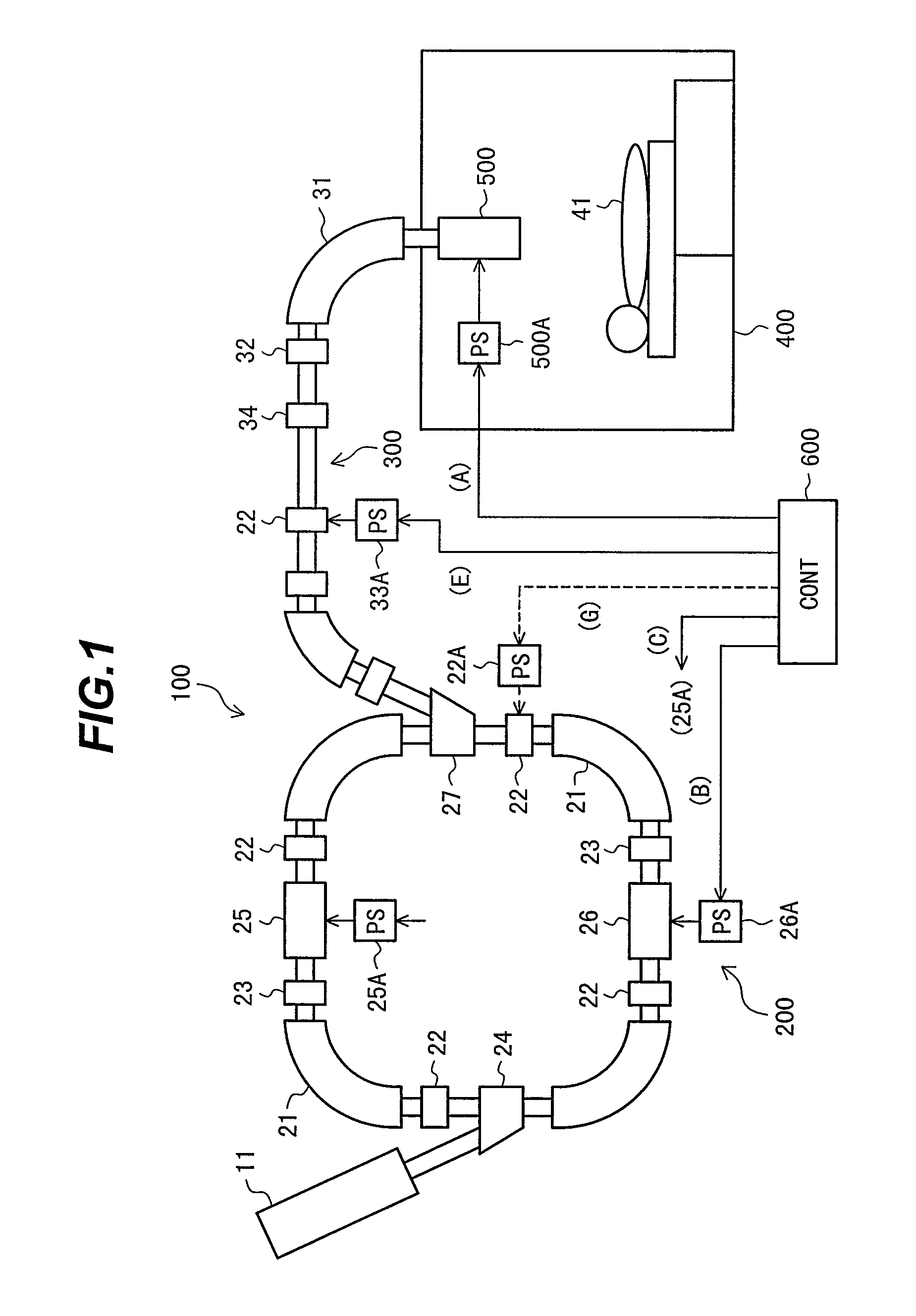
[0032]FIG. 1 is a diagram showing the configuration of the particle beam therapy system according to the first embodiment.

[0033]In FIG. 1, reference numeral 100 denotes the particle beam therapy system. The particle beam therapy system 100 includes a synchrotron 200, a beam transport system 300, an irradiation system 500 and a controller 600. The synchrotron 200 is adapted to accelerate a charged particle beam (pre-accelerated by a pre-accelerator 11 such as a linac) in order that the charged particle beam has a predetermined energy level and adapted to output the charged particle beam. The beam tr...

second embodiment

[0067]FIGS. 6A to 6F are timing charts showing operations of the particle beam therapy system in the spot scanning method in which the remote spot irradiation can be performed.

[0068]In FIGS. 6A to 6F, each of abscissa axes indicates a time t. Ordinate axes of the timing charts shown in FIGS. 6A to 6F are the same as those of the timing charts shown in FIGS. 4A to 4F, respectively.

[0069]Similarly to the example shown in FIGS. 4A to 4F, the radio frequency electromagnetic field is applied to the extraction device at the time of the spot irradiation in which the charged particle beam is supplied to the irradiation system, while the radio frequency electromagnetic field to be applied to the extraction device is turned off during the movement of the irradiation spot in which the supply of the charged particle beam to the irradiation system is blocked, as shown in FIG. 6B. In order to block the supply of the charged particle beam to the irradiation system, the supply of the charged parti...


PUM


Abstract

A particle beam therapy system using a spot scanning method includes a synchrotron, a beam transport system, an irradiation system, and a controller. A controller is configured to turn on a radio frequency electromagnetic field to be applied to an extraction system when a charged particle beam is to be supplied to the irradiation system, and turn off the radio frequency electromagnetic field to be applied to the extraction system when the supply of the charged particle beam to the irradiation system is to be blocked by means of an electromagnet provided in the beam transport system or in the synchrotron. The controller is also adapted to turn off a radio frequency acceleration voltage to be applied to an acceleration cavity in synchronization with the turning-off of the radio frequency electromagnetic field to be applied to the extraction device.

Description

BACKGROUND OF THE INVENTION[0001]1. Field of the Invention[0002]The present invention relates to a particle beam therapy system capable of high precision irradiation for treatment, and more particularly to a particle beam therapy system suitable for using a spot scanning irradiation method.[0003]2. Description of the Related Art[0004]In the recent aging society, a typical one of radiation therapies has attracted attention as one of cancer treatments since the radiation therapy is noninvasive to and has a low impact on human bodies. In addition, after the radiation therapy, the quality of life is highly maintained. Among the radiation therapies, a particle beam therapy system is a promising approach since the system provides an excellent dose concentration for an affected area of a patient. The particle beam therapy system uses a proton or a charged particle beam such as carbon, which is accelerated by an accelerator. The particle beam therapy system includes an accelerator, a beam t...

Claims


Application Information

Patent Timeline
Patent Type & Authority Patents(United States)
IPC IPC(8): A61N5/00H01J3/14
CPCH05H7/04H05H7/10H05H13/02A61N2005/1087
Inventor SAITO, KAZUYOSHISAKURABATA, HIROAKI
Owner HITACHI LTD
Why Eureka
Try Eureka