Accurate analogs for bone graft prostheses using computer generated anatomical models
What is AI technical title?
AI technical title is built by Patsnap AI team. It summarizes the technical point description of the patent document.
a computer generated anatomical model and accurate analog technology, applied in the field of cranial, facial, limb and digit muscular and bone prosthesis construction, can solve the problems of screw breaking inside the implant, not many options for its repair, and damage to the implant or abutmen
Inactive Publication Date: 2014-07-29
CLM ANALOGS LLC
View PDF79 Cites 10 Cited by
Summary
Abstract
Description
Claims
Application Information
AI Technical Summary
This helps you quickly interpret patents by identifying the three key elements:
Problems solved by technology
Method used
Benefits of technology
Benefits of technology
[0028]The first alternate embodiment uses a single axially attached rod or wing on the lower portion of the analog post. The post is then forced into a slightly undersized hole and resists both twisting and pull-out. A second embodiment using axial rod features uses two such rods on opposite sides of the analog post. A third such embodiment uses three such rods attached every 120 degrees around the bottom end of the post. Any number of such rods can be attached preferably in a symmetric array. The rods can also be enhanced in their gripping action by texturizing their outer surface; alternatively, axial grooves along their length at their outermost position can be added.
Problems solved by technology
If a prosthesis is placed into the mouth and does not seat correctly, the implant or abutment can be damaged.
If an implant is damaged there are not many options for its repair.
In cases where there have been a poor fit, the screws have broken inside the abutment requiring the replacement of the abutment.
There have been cases where the screw broke inside the implant.
The implants cannot be replaced without surgically removing them.
Placing a new implant in the same spot is not an advised option.
However, the annular wings do not hinder rotating and therefore misplacement of the analog within the replica cast stone.
Method used
Image
Click on the blue label to locate the original text in one second.
Reading with bidirectional positioning of images and text.
Examples
example
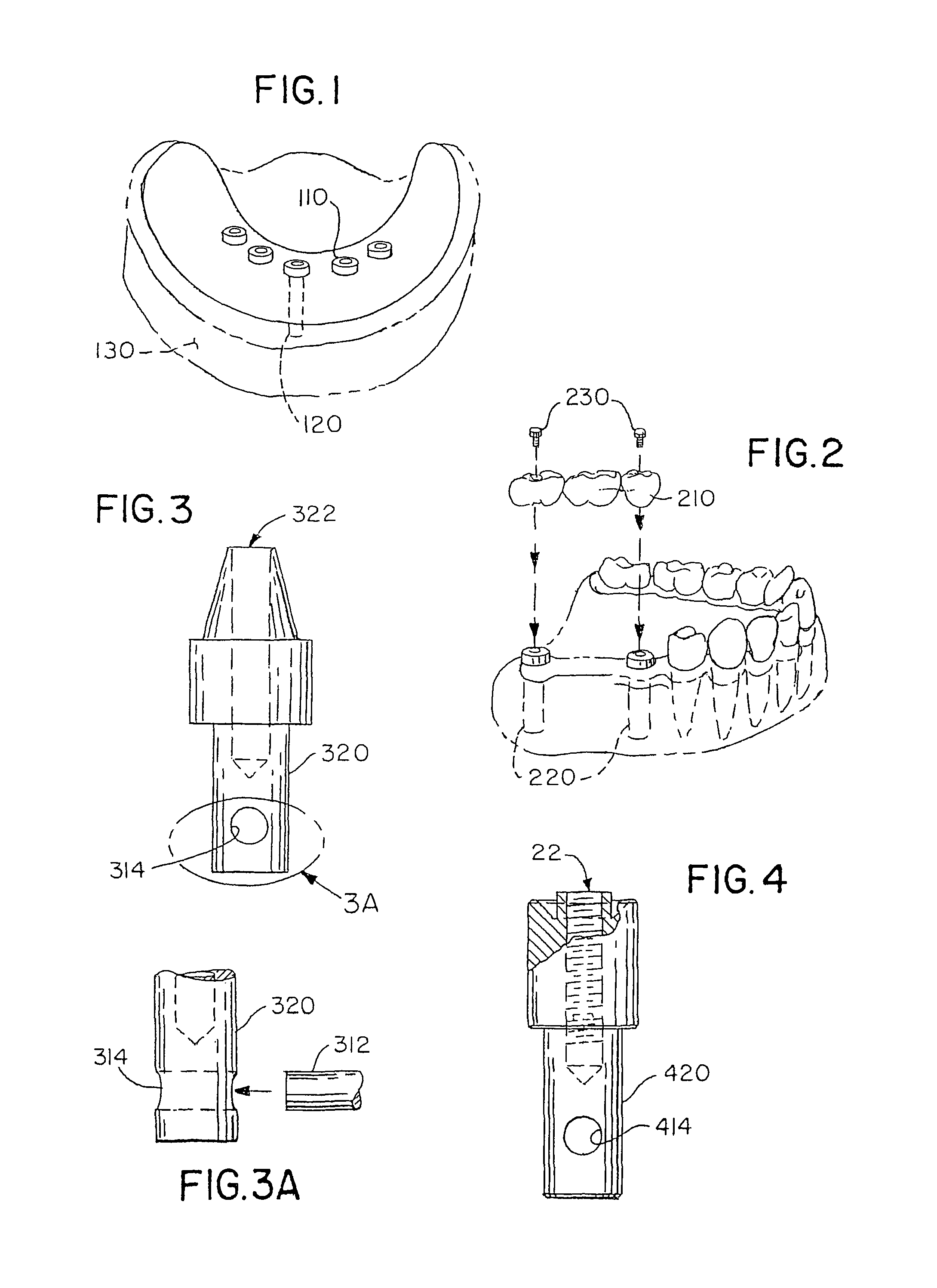
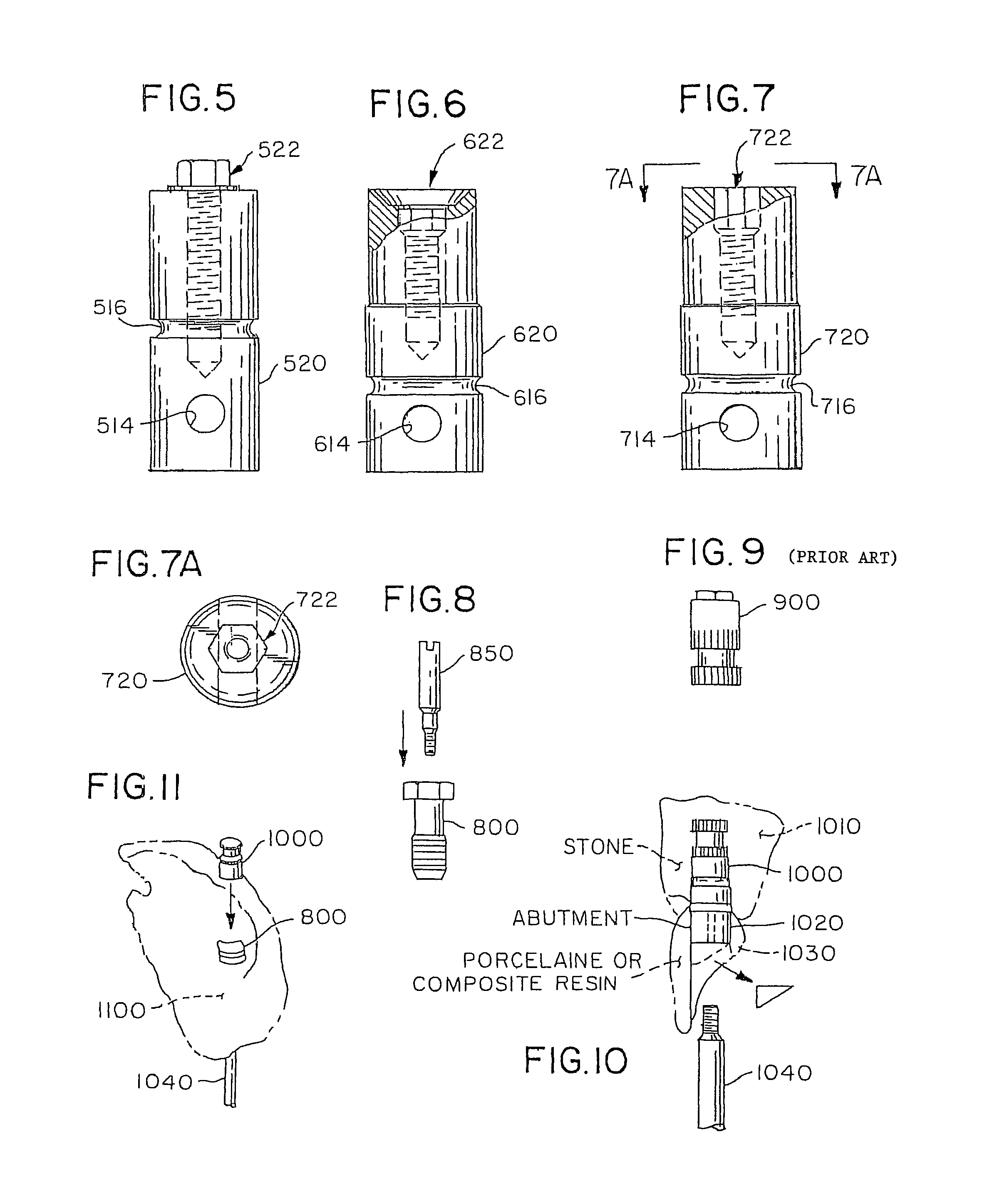
[0124]In the single tooth prosthetic work, the impression is taken from the fixture level. As shown in FIG. 8, one type of conventional impression coping 800 has an internal hexagon at the base, which corresponds to the hexagon of the abutment. The coping has depth indications for assessment of proper abutment size, 2 mm, 3 mm, 4 mm, and 5 mm. The upper margin of the abutment-like part indicates 6 mm. The impression coping is typically made of titanium.
[0125]The impression coping is used together with a special guide pin (e.g., a DCA 098), 850, for a single tooth (the guide pin used to secure the prosthesis to the implant typically has a different thread).
[0126]Typically, in the laboratory, any undercuts of the impression coping are blocked out before pouring the impression (including the depth indications). This blocking is especially important when the longest abutment is used. This precaution prevents fracturing the cast when separating the model and the impression coping.
[0127]D...
PUM
Property
Measurement
Unit
depth
aaaaa
aaaaa
depth
aaaaa
aaaaa
depth
aaaaa
aaaaa
Abstract
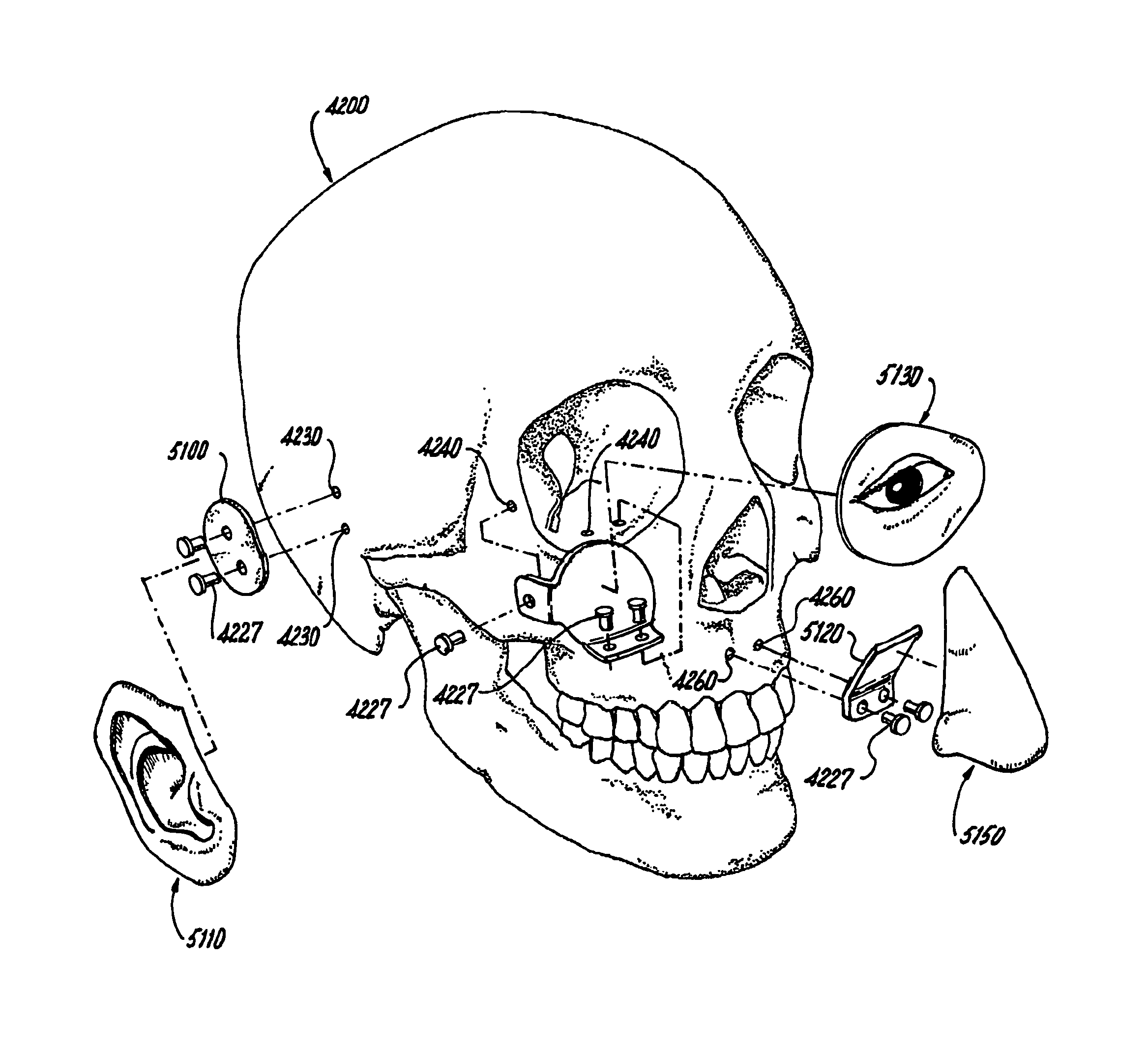
Pre-surgical planning for cranial, facial, limb and digit muscular and bone reconstruction includes preparing a computer generated anatomical model for determining a locational position for a dental implant, a surgical bone implant to repair missing bone in the cranium, limbs and digits and to install ear, eye or nose prostheses. The computer generated anatomical model is made from medical imagery and computer aided design. A surgical guide is prepared with oversize holes in registration with analogs for the dental or surgical bone implants to be inserted in the anatomical model. The surgical guide is fitted atop each analog, and bonded to the anatomical model at a predetermined angle of the analog in the anatomy. The surgical guide is removed and attached to the anatomy of a patient for accurate drilling for insertion of the implants or prostheses into the body of the patient.
Description
RELATED APPLICATIONS[0001]This application is a continuation in part of application Ser. No. 12 / 931,705 filed on Feb. 8, 2011, which application is a continuation of application Ser. No. 11 / 973,747 filed Oct. 10, 2007, now U.S. Pat. No. 7,887,327, issued Feb. 15, 2011, which application is a continuation in part of application Ser. No. 11 / 449,461, filed Jun. 8, 2006, now U.S. Pat. No. 7,281,927, issued Oct. 16, 2007 and claims priority under 35 U.S.C. 120 therefrom, which application is a continuation of application Ser. No. 10 / 056,101, filed Jan. 24, 2002, now U.S. Pat. No. 7,059,856 issued Jun. 13, 2006 and claims priority under 35 U.S.C. 120 therefrom, which application claims benefit under 35 U.S.C. 119(e) of provisional application Ser. No. 60 / 316,832 filed Aug. 31, 2001FIELD OF THE INVENTION[0002]This invention relates generally to the construction of a cranial, facial, limb and digit muscular and bone prosthesis that is attached to an implant in the body of a person.BACKGROUN...
Claims
Application Information
Patent Timeline
Application Date:The date an application was filed.
Publication Date:The date a patent or application was officially published.
First Publication Date:The earliest publication date of a patent with the same application number.
Issue Date:Publication date of the patent grant document.
PCT Entry Date:The Entry date of PCT National Phase.
Estimated Expiry Date:The statutory expiry date of a patent right according to the Patent Law, and it is the longest term of protection that the patent right can achieve without the termination of the patent right due to other reasons(Term extension factor has been taken into account ).
Invalid Date:Actual expiry date is based on effective date or publication date of legal transaction data of invalid patent.

