Power converter with reduced power dissipation

a power converter and power dissipation technology, applied in the field of power electronics, can solve the problems of not being able to distinguish a particular vendor, no satisfactory strategy has emerged to reduce the dissipation of power converters, and the cost or efficiency limitation of many vendors is not clear. to achieve the effect of reducing the power dissipation

Active Publication Date: 2014-07-29
MYPAQ HLDG LTD
View PDF457 Cites 29 Cited by
  • Summary
  • Abstract
  • Description
  • Claims
  • Application Information

AI Technical Summary

Problems solved by technology

A challenge for a power adapter designer is to provide a high level of power conversion efficiency (i.e., a low level of power adapter dissipation) over a wide range of output power.
Each of these approaches, however, provides a cost or efficiency limitation that often fails to distinguish a particular vendor in the marketplace.
Thus, despite continued size and cost reductions of components associated with power conversion, no satisfactory strategy has emerged to reduce power converter dissipation at low load currents.

Method used


Image

  • Power converter with reduced power dissipation
  • Power converter with reduced power dissipation
  • Power converter with reduced power dissipation

Examples


Embodiment Construction

[0015]The making and using of the present exemplary embodiments are discussed in detail below. It should be appreciated, however, that the present invention provides many applicable inventive concepts that can be embodied in a wide variety of specific contexts. The specific embodiments discussed are merely illustrative of specific ways to make and use the invention, and do not limit the scope of the invention.

[0016]The present invention will be described with respect to exemplary embodiments in a specific context, namely, a power adapter including a power converter operable at low load currents with reduced power dissipation. While the principles of the present invention will be described in the environment of a power converter, any application that may benefit from operation at low load with reduced power dissipation including a power amplifier or a motor controller is well within the broad scope of the present invention.

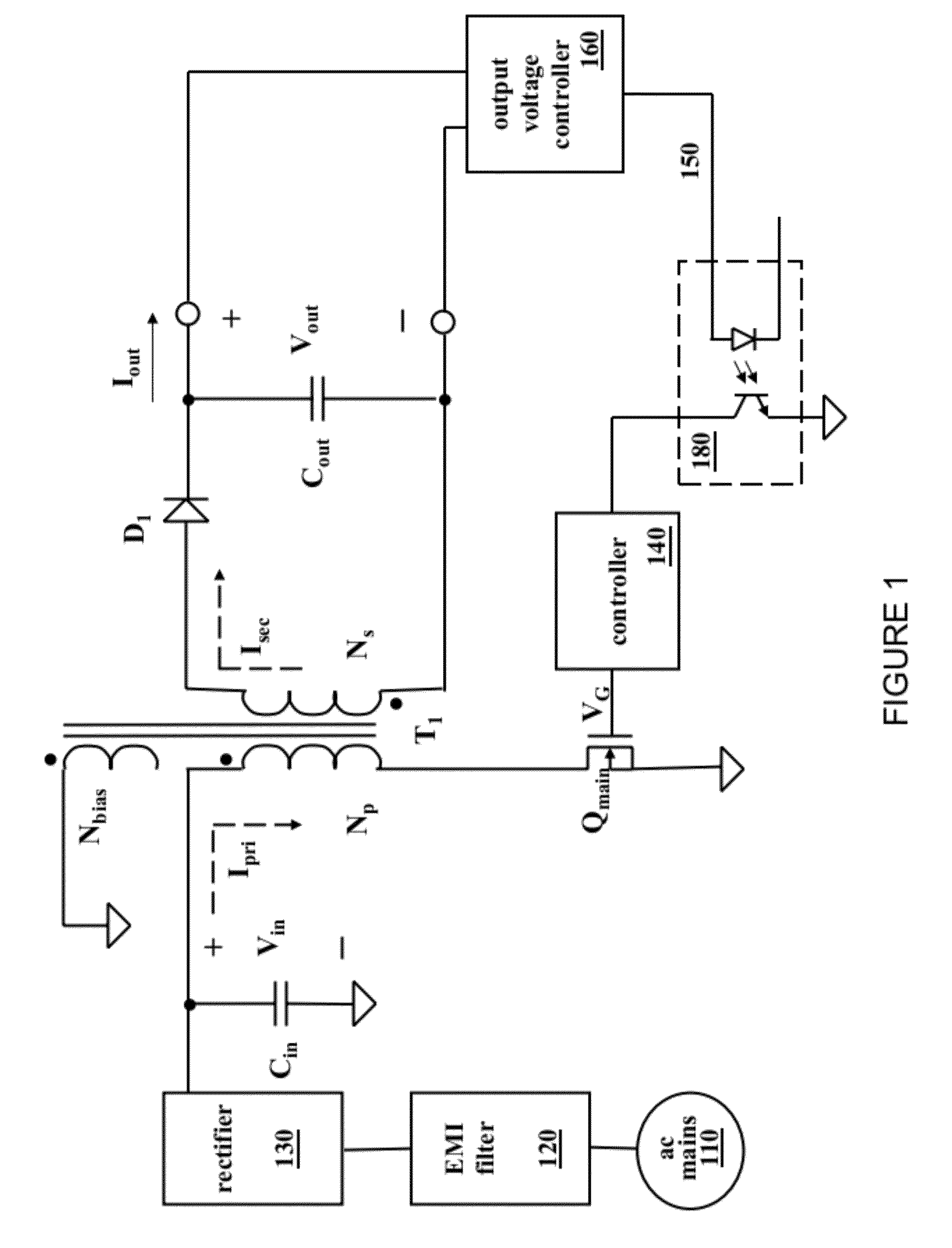
[0017]Turning now to FIG. 1, illustrated is a schematic diagr...


PUM


Abstract

A power converter with reduced power dissipation at light loads and method of operating the same. In one embodiment, the power converter includes an opto-isolator circuit configured to produce an output signal dependent on an output characteristic of the power converter. The power converter also includes a controller configured to control the output characteristic to a first regulated value when the output signal is greater than or equal to a threshold level, and control the output characteristic to a second regulated value less than the first regulated value when the output signal is less than the threshold level.

Description

TECHNICAL FIELD[0001]The present invention is directed, in general, to power electronics and, more specifically, to a power converter with reduced power dissipation at light loads.BACKGROUND[0002]A switched-mode power converter (also referred to as a “power converter”) is a power supply or power processing circuit that converts an input voltage waveform into a specified output voltage waveform. DC-DC power converters convert a direct current (“dc”) input voltage into a dc output voltage. Controllers associated with the power converters manage an operation thereof by controlling conduction periods of power switches employed therein. Generally, the controllers are coupled between an input and output of the power converter in a feedback loop configuration (also referred to as a “control loop” or “closed control loop”).[0003]Typically, the controller measures an output characteristic (e.g., an output voltage, an output current, or a combination of an output voltage and an output current...

Claims


Application Information

Patent Timeline
Patent Type & Authority Patents(United States)
IPC IPC(8): H02M3/335
CPCH02M3/33507H02M2001/0032Y02B70/16H02M1/0032Y02B70/10
Inventor BERGHEGGER, RALF, SCHRODER, GENANNT
Owner MYPAQ HLDG LTD
Why Eureka
Try Eureka