
LED lighting device

a technology of led lighting and light source, which is applied in the direction of lighting support devices, semiconductor devices for light sources, lighting and heating apparatus, etc., can solve the problems of affecting the lighting uniformity of the lighting device, reducing the life span of leds, and affecting the dielectric breakdown of leds, etc., to achieve low cost, heat dissipation effect, and low cost of insulation sheets

Inactive Publication Date: 2014-08-19
GENIUS ELECTRONICS OPTICAL CO LTD
View PDF3 Cites 0 Cited by
  • Summary
  • Abstract
  • Description
  • Claims
  • Application Information

AI Technical Summary

Benefits of technology

[0010]It is an object of the present invention to provide an LED lighting device, in which an insulation sheet is disposed between a substrate and a base, such that the shortest distance between edges of the substrate and the base measured along the surface of the insulation sheet can meet the creepage distance standards without additional manufacturing costs.
[0011]Another object of the present invention is to provide an LED lighting device, in which an insulation sheet is disposed between a substrate and a base, the insulation sheet can further have thermal conduction and conducts the heat from the substrate to the base made of metal, so as to achieve a heat dissipating effect.
[0016]By disposing an insulation sheet between a substrate and a base, the shortest distance between edges of the substrate and the base measured along the surface of the insulation sheet can meet the creepage distance standards, so as to avoid hazards caused by a lighting device which does not comply with the safety standards. In addition, the cost of the insulation sheet is low, such that the lighting device can comply with the creepage distance standards with a little cost. Besides, if the insulation sheet has thermal conduction, heat can be conducted from the substrate to the base made of metal, so as to achieve a heat dissipating effect. Preferably, the thermal conductivity of the insulation sheet is greater than or equal to 1 W / m-K, and the thickness of the insulation sheet is greater than or equal to 0.4 mm; when the thermal conductivity of the insulation sheet is less then 1 W / m-K, the insulation sheet has poor thermal conduction and unable to conduct heat to the base effectively, such that the temperature of the LED may easily beyond the working temperature, which may lower the brightness and reduce the life span of the LED. When the thickness of the insulation sheet is less than 0.4 mm, the distance through insulation will be insufficient, such that the insulation reliability will be lower and can't meet the insulation requirement, which leads to a downgrade of safety for the lighting device.

Problems solved by technology

If the creepage distance is not enough, it may incur dielectric breakdown caused by electric leakages or insulation failure.
However, because the internal resistances of each LED are different, parallel connection may cause a problem of uneven electric current, which may affect the lighting uniformity of the lighting devices and lower the life span of the LEDs.
Nevertheless, as the demand for wattage is increased, the number of LED is increased; therefore, the number of ICs is increased as well as manufacturing costs, so that it is not a perfect way to solve the problem.

Method used


Image

  • LED lighting device
  • LED lighting device
  • LED lighting device

Examples


Embodiment Construction

[0022]The detail and technical specification of the present invention will be further explained through the embodiments. However, it should be understood that the embodiments are used as examples, and should not be limited thereto.

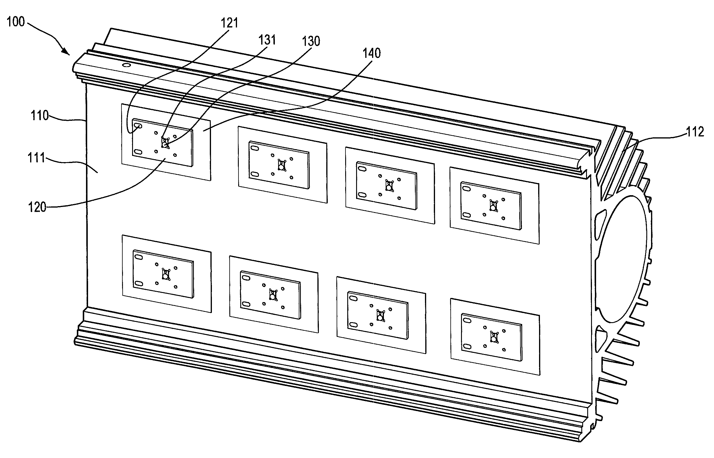
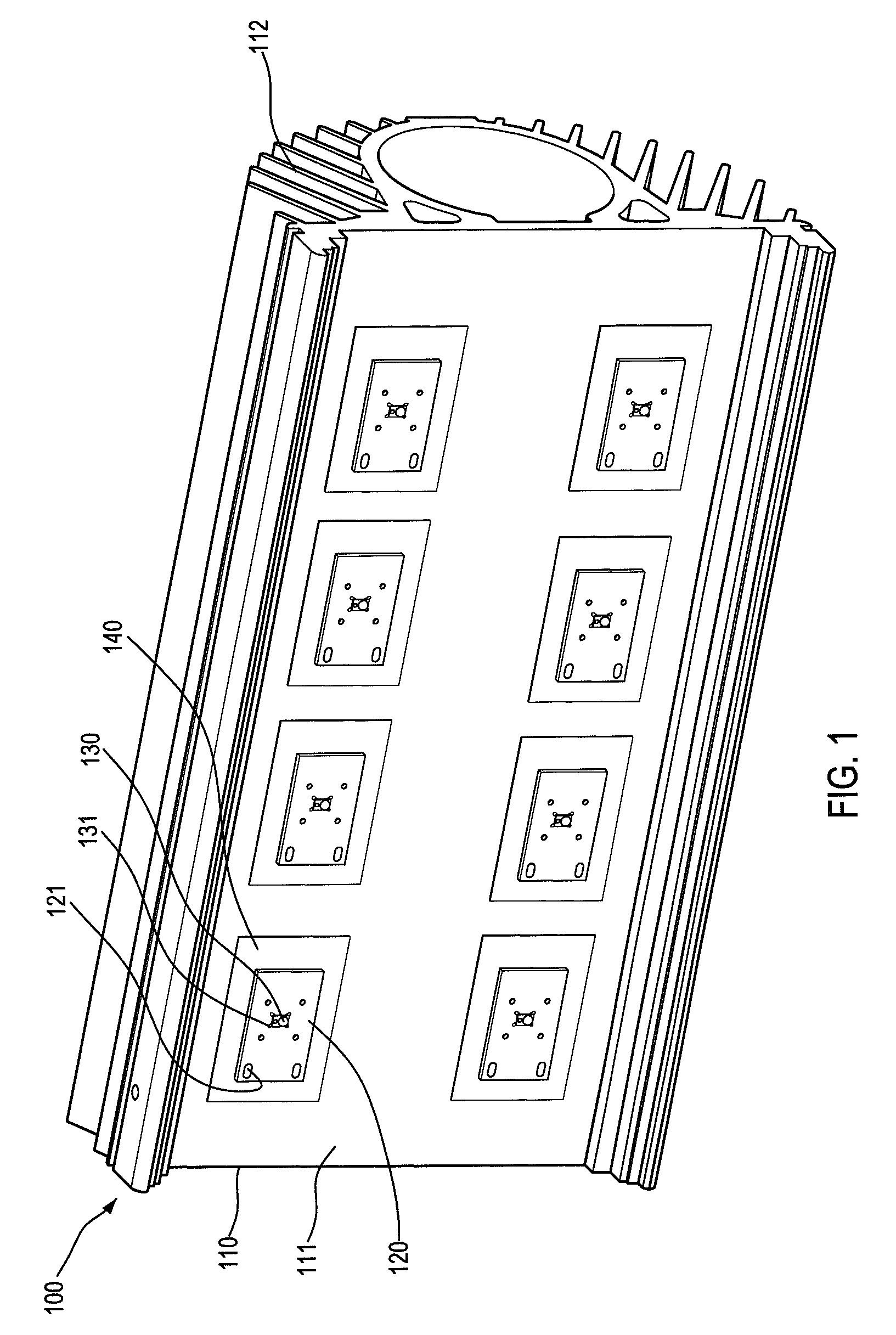
[0023]Please refer to FIGS. 1, 2, and 3, the lighting device 100 according to a first preferred embodiment of the present invention at least comprises a base 110 made of metal, and the base 110 may be used as a case of the lighting device 100. The base 110 may further comprise heat dissipation fins 112, so as to increase heat dissipation effect of the base 110.

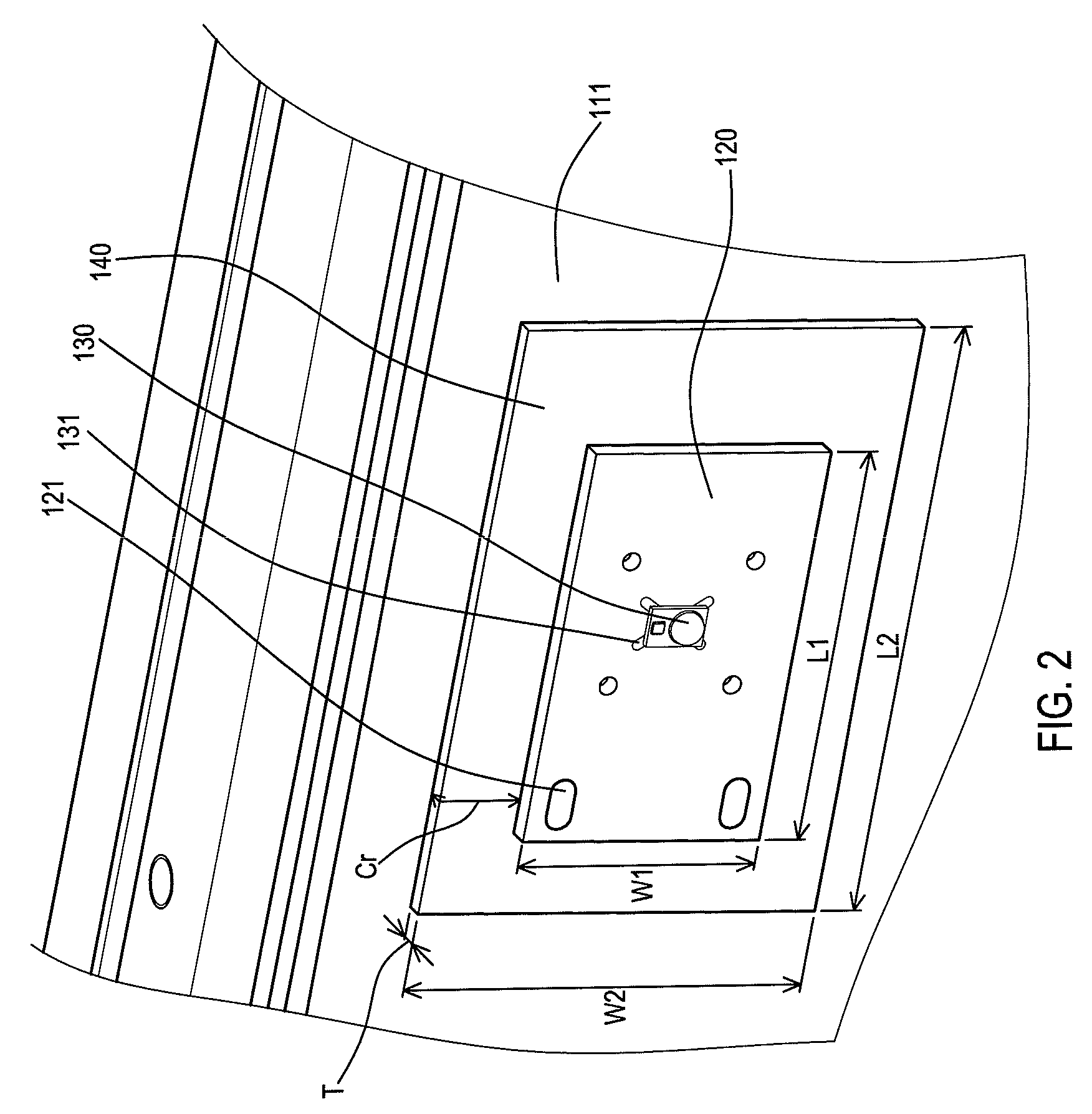
[0024]A plurality of substrates 120 are disposed on a surface 111 of the base 110 and each substrate 120 provides two electrodes 121 for electrically connecting with a main power source (not shown). A plurality of LED chips 130 are mounded on the substrates 120 and internally connected with the electrode 121.

[0025]In addition, a plurality of insulation sheet 140 are disposed between the substrates 12...


PUM


Abstract

An LED lighting device at least comprises a base made of metal materials; a substrate which is disposed on a surface of the base and has one electrode and at least one LED chip; and an insulation sheet which is disposed between the base and the substrate. The insulation sheet and the substrate satisfy the correlations L2+2×T≧L1+2×Cr, W2+2×T≧W1+2×Cr and Cr≧1.6 mm. By controlling the dimension of the insulation sheet, a creepage distance between the electrode and the base can be increased, so as to solve the safety problem of lighting devices without increasing manufacturing costs.

Description

INCORPORATION BY REFERENCE[0001]This application claims priority from Taiwan Patent Application No. 101119564, filed on May 31, 2012, the contents of which are hereby incorporated by reference in their entirety for all purposes.BACKGROUND OF THE INVENTION[0002]1. Field of Invention[0003]The present invention is related to an LED lighting device, and more particularly to a lighting device which needs to comply with the safety standards of minimum creepage distances.[0004]2. Related Art[0005]Currently, for achieving the requirements of energy saving and environmental protection, the manufactures and the research & development unit of the lighting devices are gradually adopting LEDs as the light source of lighting devices. LED is a solid-state semiconductor device that can convert electrical energy directly into light. The LEDs have the advantages of small volume, fast response speed, low power consuming, and low pollution.[0006]However, the lighting devices belong to electronic produc...

Claims


Application Information

Patent Timeline
Patent Type & Authority Patents(United States)
IPC IPC(8): F21S4/00F21V29/15
CPCF21V29/00F21V29/15F21V15/06F21V29/74F21Y2101/02F21Y2103/003F21Y2103/10F21Y2115/10
Inventor HSU, HUI-JULIU, HONG-PINGHO, YEN-WEI
Owner GENIUS ELECTRONICS OPTICAL CO LTD
Learn More