
Hoist

a technology of a hoist and a rotor is applied in the field of hoists, which can solve the problems of increasing heat generated by the inverter controller, affecting normal operation, and affecting normal operation, so as to and improve the heat dissipation

Active Publication Date: 2015-06-02
KITO CORP
View PDF18 Cites 3 Cited by
  • Summary
  • Abstract
  • Description
  • Claims
  • Application Information

AI Technical Summary

Benefits of technology

The present invention is about improving heat dissipation in a hoist by taking into account the arrangement and configuration of heat sources. This allows the hoist to operate more frequently, which is the objective of the invention. The improvements focus on making the mechanism compact and efficient for heat dissipation. In summary, the patent aims to provide a hoist that effectively dissipates heat and has a compact mechanism.

Problems solved by technology

In such a hoist, the inverter controller and other various heat sources (a motor, a regenerative resistor and the like) are accommodated in a casing, and heat generated during an operation has been problematic.
For example, heat generated by the inverter controller increases, particularly at the time of a high-load operation.
The heat affects a constituent element such as a power transistor of the inverter controller or the like, possibly hindering a normal operation.

Method used


Image

  • Hoist
  • Hoist
  • Hoist

Examples


first embodiment

[First Embodiment]

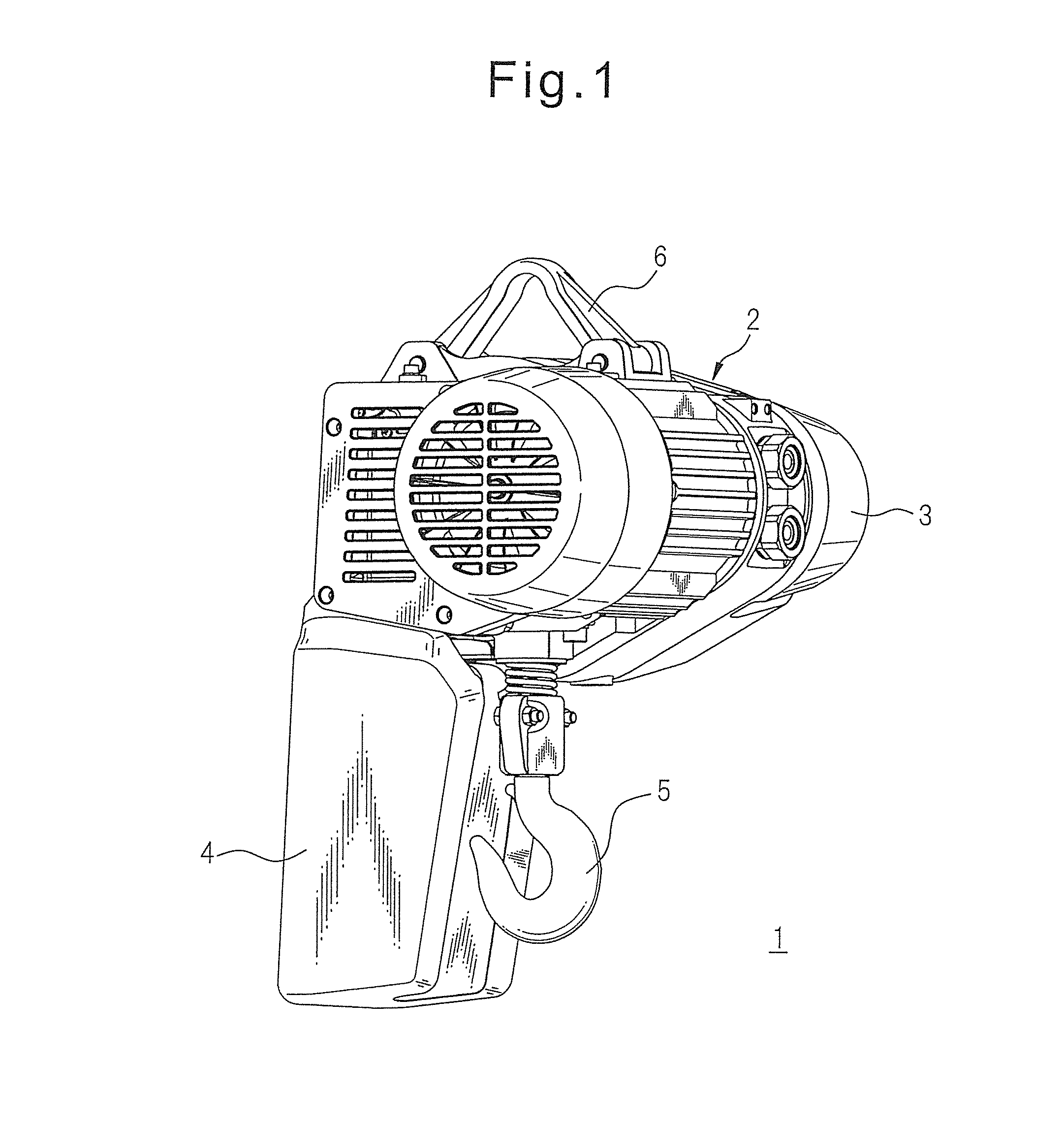
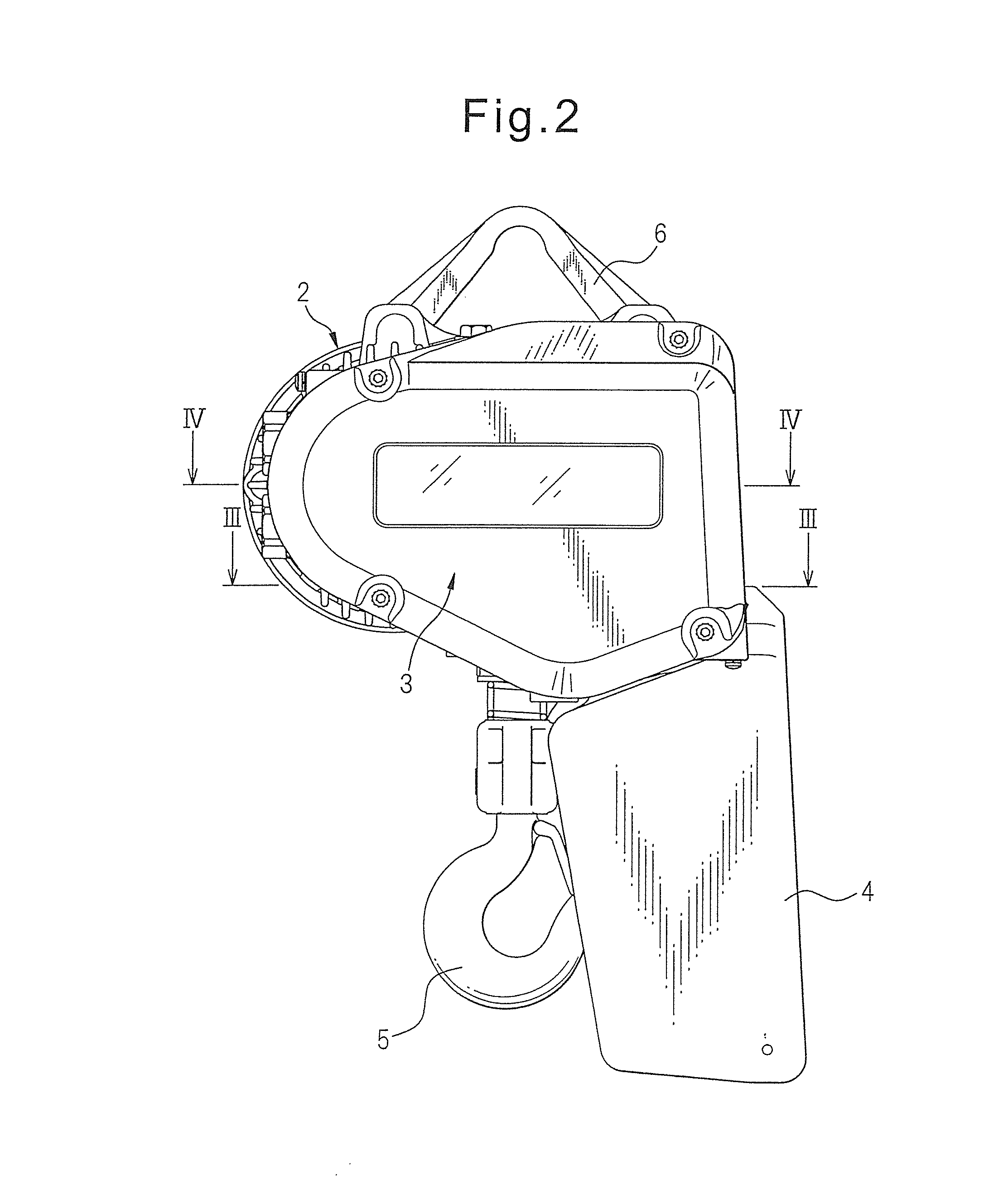
[0030]FIGS. 1 and 2 illustrate a hoist 1 according to a first embodiment of the present invention.

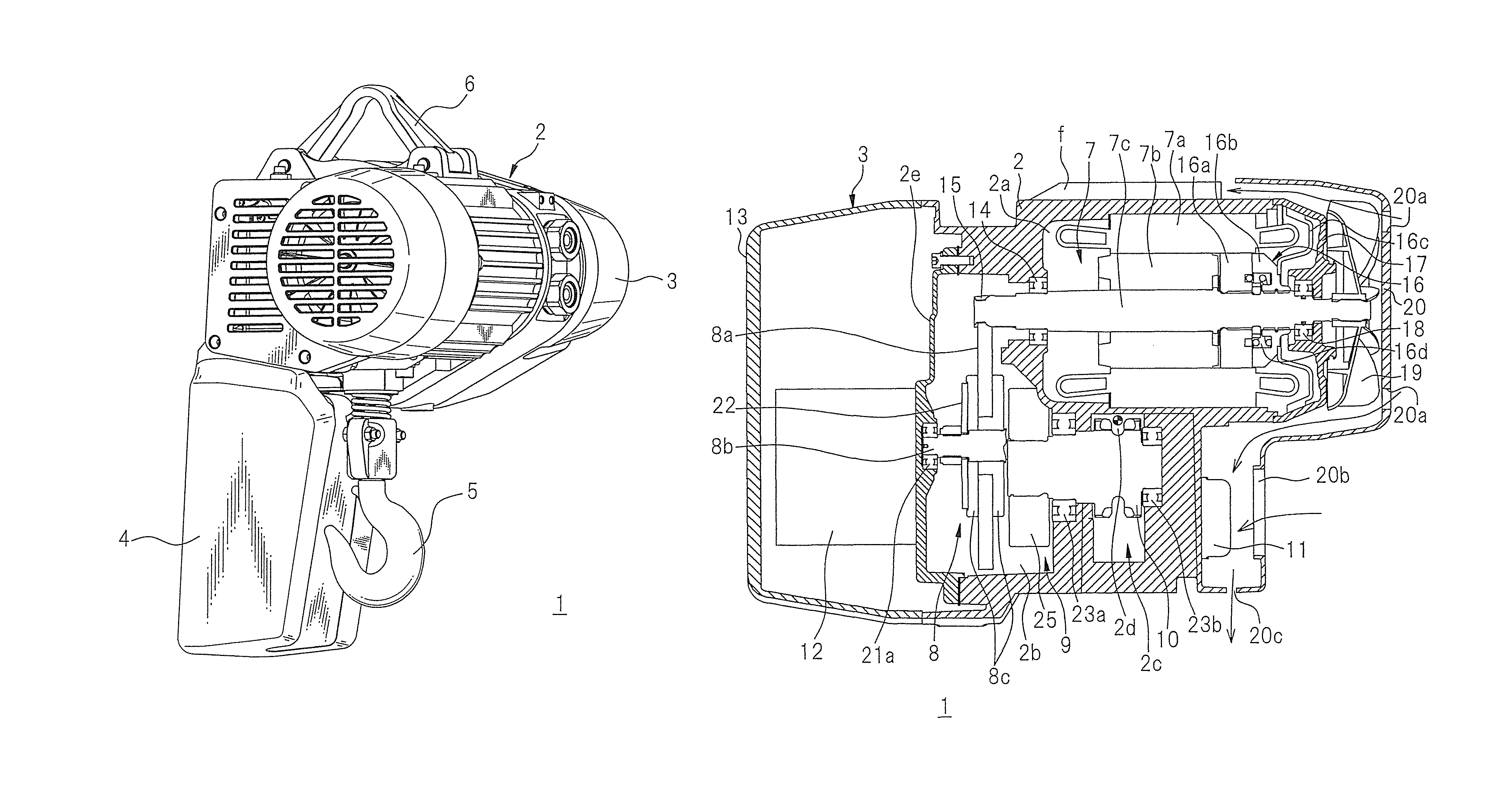
[0031]The hoist 1 is an inverter-driven electric chain hoist including a motor for lifting and lowering a load, the motor being driven by an inverter controller, a mechanism unit which includes a reduction gear mechanism and a load sheave for winching up and down a chain with power transmitted from the reduction gear mechanism, and a casing 2 for accommodating the motor and the mechanism unit as described below. The casing 2 is provided with an electrical component accommodating unit 3 adjacent thereto, and the electrical component accommodating unit 3 accommodates electrical components of the inverter controller, a control circuit or the like. In addition, a chain bucket 4 for accommodating a chain is integrally attached to the casing 2. The chain bucket 4 carries a hook unit 5 on a side thereof, and the hook unit 5 is adapted to winch up and down a load by the chain ...

second embodiment

[Second Embodiment]

[0075]A hoist according to the present invention can also be embodied by a hoist 1 illustrated in FIG. 6.

[0076]This hoist 1 has the same basic configuration as the hoist 1 according to the first embodiment with regard to the arrangement of the motor 7, the reduction gear mechanism 8 and the load sheave 10 in the casing 2 and the arrangement of the inverter controller 12 and the regenerative resistance unit 11. Thus, a description of these arrangements will be omitted.

[0077]As illustrated in FIG. 6, in the hoist 1 according to the second embodiment, a fan 30 is provided at an end of the motor shaft 7c of the motor 7 close to the inverter controller 12, in order to directly cool the inverter controller 12 with air.

[0078]In this case, the motor shaft 7c of the motor 7 protrudes from the casing cover 2e partitioning the mechanism chamber 2b that accommodates the reduction gear mechanism 8 and extends in the electrical component accommodating unit 3.

[0079]The controlle...


PUM


Abstract

A hoist with a regenerative resistor contains the following in a casing: a load-raising / lowering motor driven by an inverter control device and provided with a forced-cooling means; and a mechanism part containing a reduction mechanism part and a load sheave that uses power from the reduction mechanism part to take up and let out a chain. The load-raising / lowering motor, mechanism part, inverter control device, and regenerative resistor are distributed inside the casing to achieve a balance of weight about the center of gravity of the load applied when raising or lowering. Also, the inverter control device and the regenerative resistor are affixed to the casing, in close contact therewith, in parts of the casing separated from each other with the mechanism part therebetween.

Description

CROSS-REFERENCE TO RELATED APPLICATION[0001]This application is a National Phase Patent Application and claims the priority of International Application No. PCT / JP2011 / 076924 filed on Nov. 22, 2011, which claims priority to and benefit of Japanese Patent Application No. 2010-262814 filed on Nov. 25, 2010, the entire disclosures of which are incorporated herein by reference.FIELD OF THE INVENTION[0002]The present invention relates to a hoist, such as an electric chain hoist and an electric hoist, in which an electric motor is driven by an incorporated inverter controller in order to lift and lower a load. In particular, the present invention relates to a hoist for which an arrangement and a configuration of a heat source such as an inverter controller, a motor, a regenerative resistor and the like are taken into account, and a forced cooling means is used to provide a heat dissipation effect.BACKGROUND ART[0003]A hoist, such as an electric chain hoist and an electric hoist, includes ...

Claims


Application Information

Patent Timeline
Patent Type & Authority Patents(United States)
IPC IPC(8): B66D1/12H02K9/04B66D3/20B66D3/26H02K7/116
CPCH02K9/04B66D3/20B66D3/26H02K7/116H02K7/106H02K9/06H02K11/0094H02K11/33B66D1/12B66D1/28
Inventor HIROSHIMA, TETSU
Owner KITO CORP
Learn More