Centrifugal deaerator for a turbomachine

a centrifugal deaerator and turbomachine technology, which is applied in centrifuges, separation processes, filtration separation, etc., can solve the problems of low degree of penetration of air particles in foam, associated risk of leakage, and metal foam acting as a wall

Active Publication Date: 2022-08-02
SAFRAN HELICOPTER ENGINES
View PDF16 Cites 0 Cited by
  • Summary
  • Abstract
  • Description
  • Claims
  • Application Information

AI Technical Summary

Benefits of technology

[0019]A deaerator equipped with a metal foam, such as a foam commercialised under the name Retimet®, allows forming a potential substantial contact surface with the air / oil mixture which allows improving the probability of capturing an oil particle which is then centrifugated outside of the deaerator. These foams act as a filter. Furthermore, the centrifugal effect allows avoiding the saturation of filters by the continuous evacuation of oil drops attached to the filters.
[0041]A turboshaft according to the invention equipped with a deaerator according to the invention therefore consumes less oil than a turboshaft of the prior art by an improved oil recovery. A turboshaft according to the invention presents a lighter weight than a turboshaft of the prior art. The duration of a mission of a helicopter equipped with turboshafts according to the invention is therefore longer. Furthermore, the maintenance operations are less frequent. Finally, the ecological impact of a turboshaft according to the invention is better than that of the turboshafts of the prior art.

Problems solved by technology

One of the disadvantages, however, of these metal form deaerators resides in the fact that at high speed (for example, for speeds of around 6000 revolutions per minutes) and even more so at a very high speed (for example, for speeds of around 25,000 revolutions per minutes), the front surface constituted by the metal foam acts as a wall and the degree of penetration of the air particles in the foam is low.
This comes out as substantial load losses at a high speed, that the secondary air system of the turbomachine cannot support with the associate risk of leakage by the sealings of the generator.

Method used


Image

  • Centrifugal deaerator for a turbomachine
  • Centrifugal deaerator for a turbomachine

Examples


Embodiment Construction

[0047]In the figures, the scales and proportions are not strictly adhered to and this, for purposes of illustration and clarity.

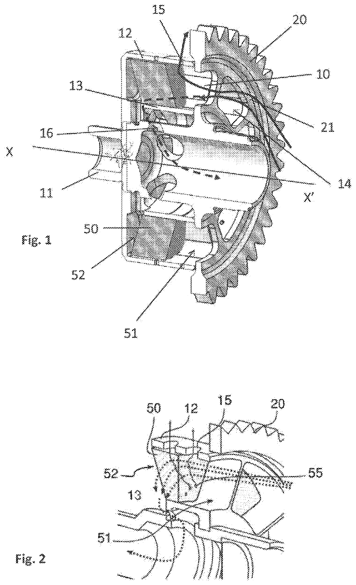
[0048]A deaerator according to the invention comprises, such as represented in FIG. 1, an annular housing 10 for the centrifugal separation of an air / oil mixture arranged around a hollow shaft 11. This annular housing 10 is delimited by an outer annular wall 12 and an inner annular wall 13. This housing 10 comprises a plurality of deaerating compartments distributed around the hollow shaft 11.

[0049]The deaerator further comprises a plurality of axial inlets 14 allowing the air / oil mixture to enter into the housing 10. Each compartment of the housing 10 is connected to an axial inlet 14 such that each compartment can receive a mixture to be separated by a dedicated inlet.

[0050]The deaerator further comprises a plurality of radial oil outlets 15 arranged in the outer wall 12 and configured to be able to evacuate the oil separated from the mixture by the effec...


PUM

PropertyMeasurementUnit
rotationaaaaaaaaaa
thicknessaaaaaaaaaa
pressureaaaaaaaaaa

Abstract

The invention relates to a centrifugal deaerator for an air / oil mixture of a turbomachine, comprising: an annular housing (10) for the centrifugal separation of said mixture, arranged around a hollow shaft (11); axial inlets (14) for the flow of said air / oil mixture into said housing (10); a pinion (20) for rotating said housing (10); and radial oil outlets (15) and oil-free air outlets (16), characterised in that it comprises a metal foam (50) housed in said housing (10) by partially extending along the axial direction (XX′) so as to define two successive spaces, a foam-free space (51) and a foam-lined space (52), said foam-free space opening up towards said axial inlets. A device can be advantageously added to the hollow shaft in order to reduce the free-vortex phenomenon and to thereby significantly reduce the load losses of the deaerator.

Description

1. TECHNICAL FIELD OF THE INVENTION[0001]The invention relates to a centrifugal deaerator for a turbomachine.2. TECHNOLOGICAL BACKGROUND[0002]The state of the art comprises, in particular, patent applications published under the numbers US-A1-2015 / 007531, FR-A1-3 007 463 and US-A1-2016 / 208650, as well as U.S. Pat. No. 5,716,423.[0003]Turbomachines are complex systems which implement a certain number of rotating assemblies (turbines, compressor, etc.) which must be equipped with sealing devices. These sealing devices are generally produced by pressurized air labyrinths arranged in the vicinity of the rotating assembly. To do this, an air is taken directly in the air duct of the turbomachine. This air then transits in the turbomachine by the different labyrinths provided for this purpose, then is evacuated towards the outside of the turbomachine to limit the increase in pressure of the other zones of the turbomachine, in particular the reduction gear, the accessory box, etc. However, ...

Claims


Application Information

Patent Timeline
Patent Type & Authority Patents(United States)
IPC IPC(8): B04B5/10F02C7/06B01D39/20B01D45/16B01D46/00B04B5/00B04B5/08B01D50/20
CPCF02C7/06B01D39/2051B01D45/16B01D46/0031B01D50/20B04B5/005B04B5/08F05D2220/30F05D2260/609
Inventor PAJARD, JEAN-PIERRECAZAUX, YANNICKFULLERINGER, BENJAMIN
Owner SAFRAN HELICOPTER ENGINES
Why Eureka
Try Eureka