Self-Centering Wafer Carrier System For Chemical Vapor Deposition

a carrier system and chemical vapor deposition technology, applied in chemical vapor deposition coating, semiconductor/solid-state device testing/measurement, coatings, etc., can solve problems such as non-uniform deposited films

Active Publication Date: 2016-12-22
VEECO INSTR
View PDF2 Cites 254 Cited by
  • Summary
  • Abstract
  • Description
  • Claims
  • Application Information

AI Technical Summary

Problems solved by technology

The presence of non-uniform temperature profiles across the su

Method used


Image

  • Self-Centering Wafer Carrier System For Chemical Vapor Deposition
  • Self-Centering Wafer Carrier System For Chemical Vapor Deposition
  • Self-Centering Wafer Carrier System For Chemical Vapor Deposition

Examples


Embodiment Construction

[0067]The present teaching will now be described in more detail with reference to exemplary embodiments thereof as shown in the accompanying drawings. Reference in the specification to “one embodiment” or “an embodiment” means that a particular feature, structure, or characteristic, described in connection with the embodiment is included in at least one embodiment of the teaching. The appearances of the phrase “in one embodiment” in various places in the specification are not necessarily all referring to the same embodiment.

[0068]While the present teachings are described in conjunction with various embodiments and examples, it is not intended that the present teachings be limited to such embodiments. On the contrary, the present teachings encompass various alternatives, modifications, and equivalents, as will be appreciated by those of skill in the art. Those of ordinary skill in the art, having access to the teaching herein, will recognize additional implementations, modifications,...


PUM

PropertyMeasurementUnit
Temperatureaaaaaaaaaa
Pressureaaaaaaaaaa
Centrifugal forceaaaaaaaaaa

Abstract

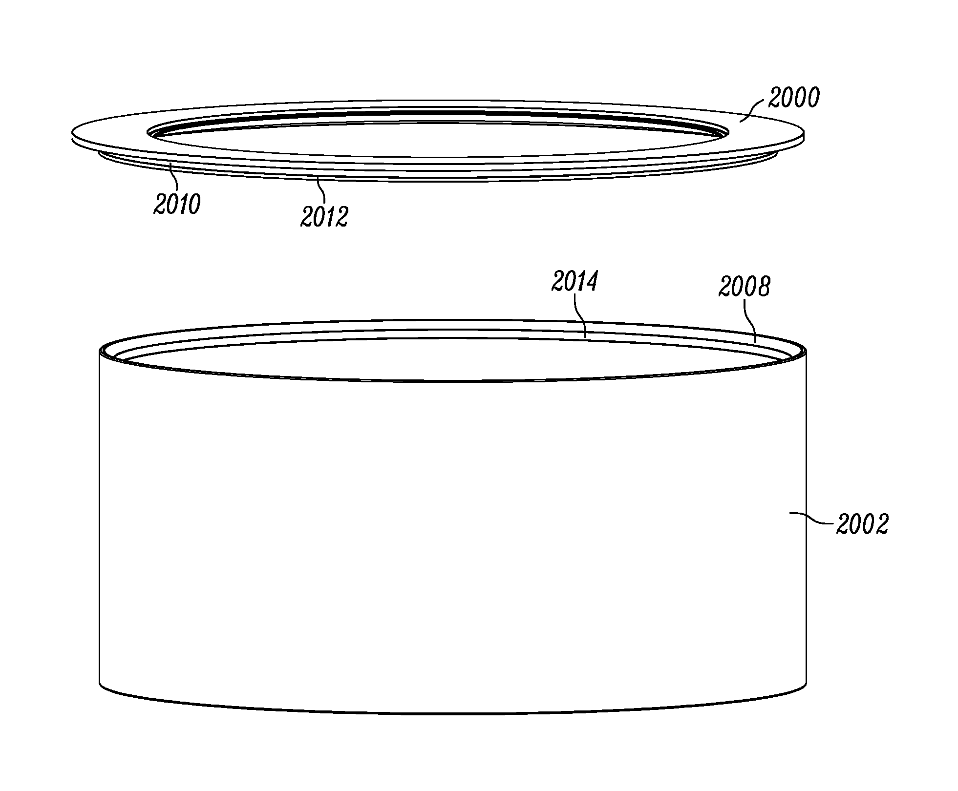
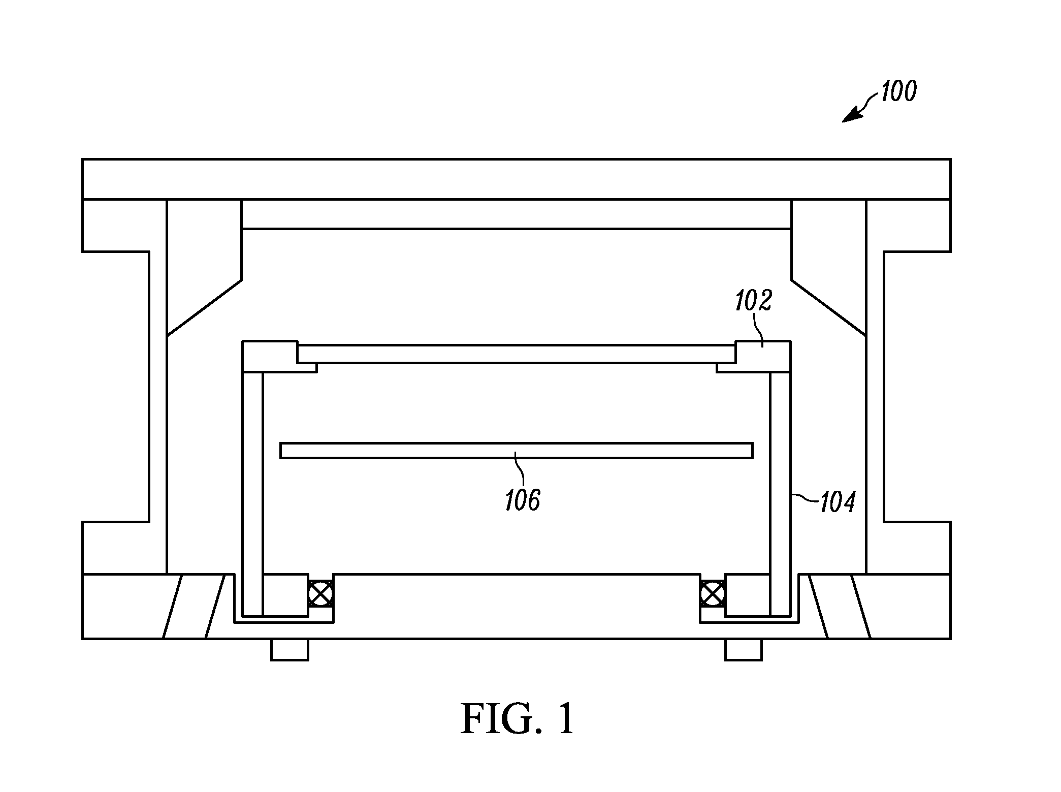
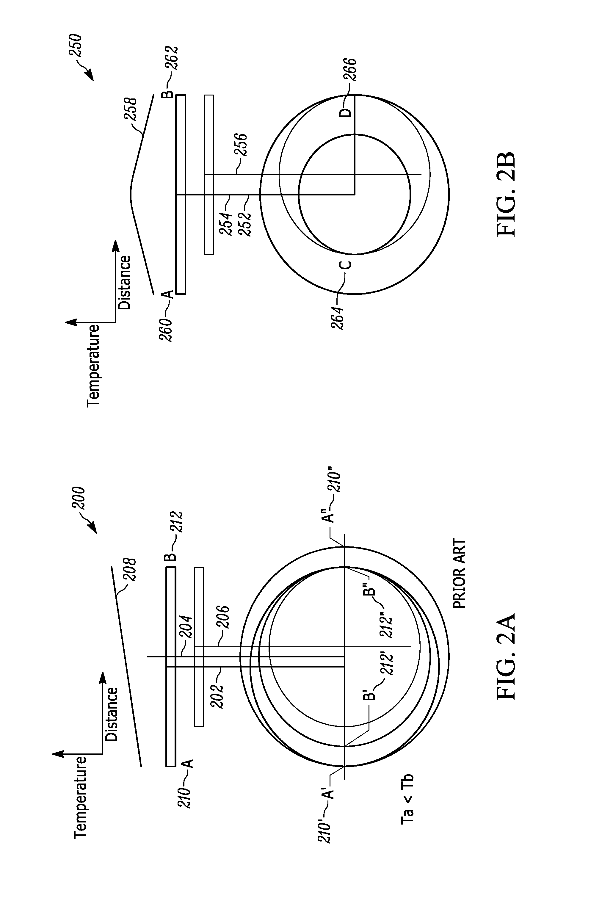
A self-centering wafer carrier system for a chemical vapor deposition (CVD) reactor includes a wafer carrier comprising an edge. The wafer carrier at least partially supports a wafer for CVD processing. A rotating tube comprises an edge that supports the wafer carrier during processing. An edge geometry of the wafer carrier and an edge geometry of the rotating tube being chosen to provide a coincident alignment of a central axis of the wafer carrier and a rotation axis of the rotating tube during process at a desired process temperature.

Description

CROSS REFERENCE TO RELATED APPLICATION[0001]The present application is a non-provisional patent application of U.S. Provisional Patent Application No. 62 / 298,540 entitled “Self-Centering Wafer Carrier System for Chemical Vapor Deposition”, filed on Feb. 23, 2016; U.S. Provisional Patent Application Ser. No. 62 / 241,482, entitled “Self-Centering Wafer Carrier System for Chemical Vapor Deposition”, filed Oct. 14, 2015; and U.S. Provisional Patent Application Ser. No. 62 / 183,166, entitled “Self-Centering Wafer Carrier System for Chemical Vapor Deposition”, filed Jun. 22, 2015. The entire contents of U.S. Provisional Patent Application Nos. 62 / 298,540, 62 / 241,482, and 62 / 183,166 and are herein incorporated by reference.[0002]The section headings used herein are for organizational purposes only and should not be construed as limiting the subject matter described in the present application in any way.INTRODUCTION[0003]Many material processing systems include substrate carriers for supporti...

Claims


Application Information

Patent Timeline
IPC IPC(8): H01L21/02H01L21/67H01L21/687
CPCH01L21/0262H01L21/68735H01L21/68757C23C16/455H01L21/02271H01L21/28556H01L21/67098C23C16/458C23C16/4583C23C16/46H01L21/68H01L21/683H01L21/687H01L21/68714H01L21/68785H01L21/67103H01L21/67109H01L21/68792C23C16/4584C23C16/4585H01L21/205H01L21/02046H01L21/0228H01L21/6773H01L21/682H01L21/6835H01L21/68764H01L21/67248H01L22/12
Inventor KRISHNAN, SANDEEPGURARY, ALEXANDER I.CHANG, CHENGHUNG PAULMARCELO, EARL
Owner VEECO INSTR
Why Eureka
Try Eureka