
Overvoltage protection for a motor vehicle electrical system in the event of a load dump

a technology for motor vehicles and electrical systems, applied in the direction of engine-driven generators, battery/cell propulsion, transportation and packaging, etc., can solve the problems of no integrated arresting function with sufficient robustness, controllable or active switching elements, and components in the motor vehicle electrical system may be damaged, etc., to achieve less stress, less damage, and less stress

Active Publication Date: 2018-05-29
SEG AUTOMOTIVE GERMANY GMBH
View PDF28 Cites 0 Cited by
  • Summary
  • Abstract
  • Description
  • Claims
  • Application Information

AI Technical Summary

Benefits of technology

[0011]The present invention is directed to a motor vehicle electrical system which includes an electric machine, an active bridge rectifier, and at least one control device. As is customary in this regard, the at least one control device is configured for converting an alternating voltage which is output by the electric machine at a number of phase connections into a direct voltage by controlling active switching elements of the bridge rectifier. In addition, an arrangement is provided which is configured for initiating a short circuit of at least two of the phase connections as soon as a signal characterizing the direct voltage exceeds an upper threshold value, and for eliminating the short circuit as soon as the signal characterizing the direct voltage subsequently falls below a lower threshold value.
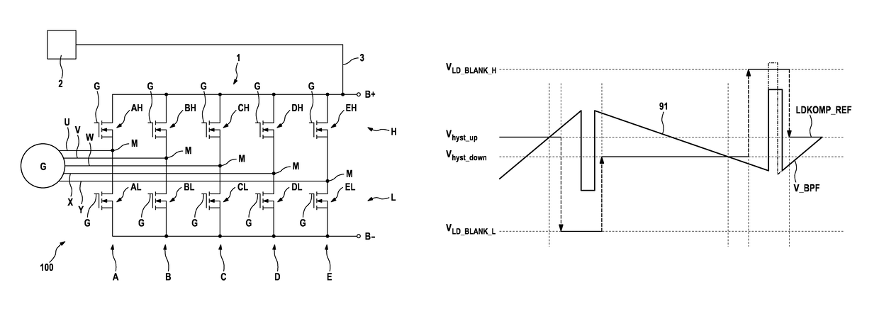
[0014]However, according to the present invention, it is also provided to filter the detected value and to provide the filtered value as the signal characterizing the direct voltage. As explained below and in particular shown with reference to FIGS. 3 through 5, the measures according to the present invention allow high-frequency repetitive switchover operations between a short circuit and an eliminated short circuit to be avoided. The active switching elements of a corresponding bridge rectifier are exposed to less stress due to use of the measures according to the present invention.
[0015]In other words, the undesirable activation and deactivation of the phase short circuit, which typically take place in rapid succession, due to the voltage peaks of the voltage signal output by the active bridge rectifier in each case rising above and falling below the trigger thresholds used, are prevented in that a voltage signal is filtered with an appropriately adapted filter, and / or an adaptive control of trigger thresholds of a corresponding comparator, which is part of the mentioned evaluation element, takes place. A significant advantage of the measures provided according to the present invention is the avoidance of frequent switching operations in the active switching elements used, for example the MOSFETs installed in an active bridge rectifier, which could result in intense, possibly damaging stress. The installed switching elements may therefore have a smaller, more cost-effective design.
[0018]Within the scope of the present invention, a comparator having a settable comparator threshold may also be used in a particularly advantageous manner. If the comparator threshold is set to an upper value, this value may correspond to the upper threshold value. Similarly, if the comparator threshold is set to a lower value, this value may correspond to the lower threshold value. To prevent undesirably frequent switching operations, in particular it may also be provided to lower the lower threshold value for a predetermined time period as soon as the signal characterizing the direct voltage exceeds the upper threshold value, or to raise the upper threshold value for a predetermined time period as soon as the signal characterizing the direct voltage subsequently exceeds the lower threshold value. This avoids the situation in which the mentioned signal crosses a particular threshold value multiple times within the indicated time period, thus resulting in switching of the involved active switching elements. Instead of lowering or raising a particular value of the comparator threshold, it may also be provided to virtually deactivate the particular threshold values in some other way, if such a comparator is designed for such an operation. The aim in each case is to avoid crossing of a particular threshold value during a predetermined time period, which is selected based on characteristics of the particular vehicle electrical system, for example based on resistance, inductance, and capacitance values.
[0020]In addition, the implementation of the method in the form of software is advantageous, since this entails particularly low costs, in particular when an executing control unit may also be used for other tasks, and therefore is present anyway. Suitable data carriers for providing the computer program are in particular diskettes, hard drives, flash memories, EEPROMs, CD-ROMs, DVDs, and others. In addition, downloading a program via computer networks (Internet, intranet, etc.) is possible.

Problems solved by technology

If it is not possible to intercept or completely intercept these high voltages by capacitively acting elements in the direct voltage network (for example, the motor vehicle battery) or in the rectifier, components in the motor vehicle electrical system may be damaged due to overvoltages.
However, presently available controllable or active switching elements for such active bridge rectifiers, for example MOSFETs, have no integrated arresting function with sufficient robustness, as is the case for conventional rectifier Zener diodes, and therefore are not able to intercept the overvoltage.
Problems may thus arise here, since the mentioned switching operations, i.e., repeating phase short circuits, result in heavy stress on the involved switching elements.
This may damage the switching elements when they are not appropriately dimensioned.

Method used


Image

  • Overvoltage protection for a motor vehicle electrical system in the event of a load dump
  • Overvoltage protection for a motor vehicle electrical system in the event of a load dump
  • Overvoltage protection for a motor vehicle electrical system in the event of a load dump

Examples


Embodiment Construction

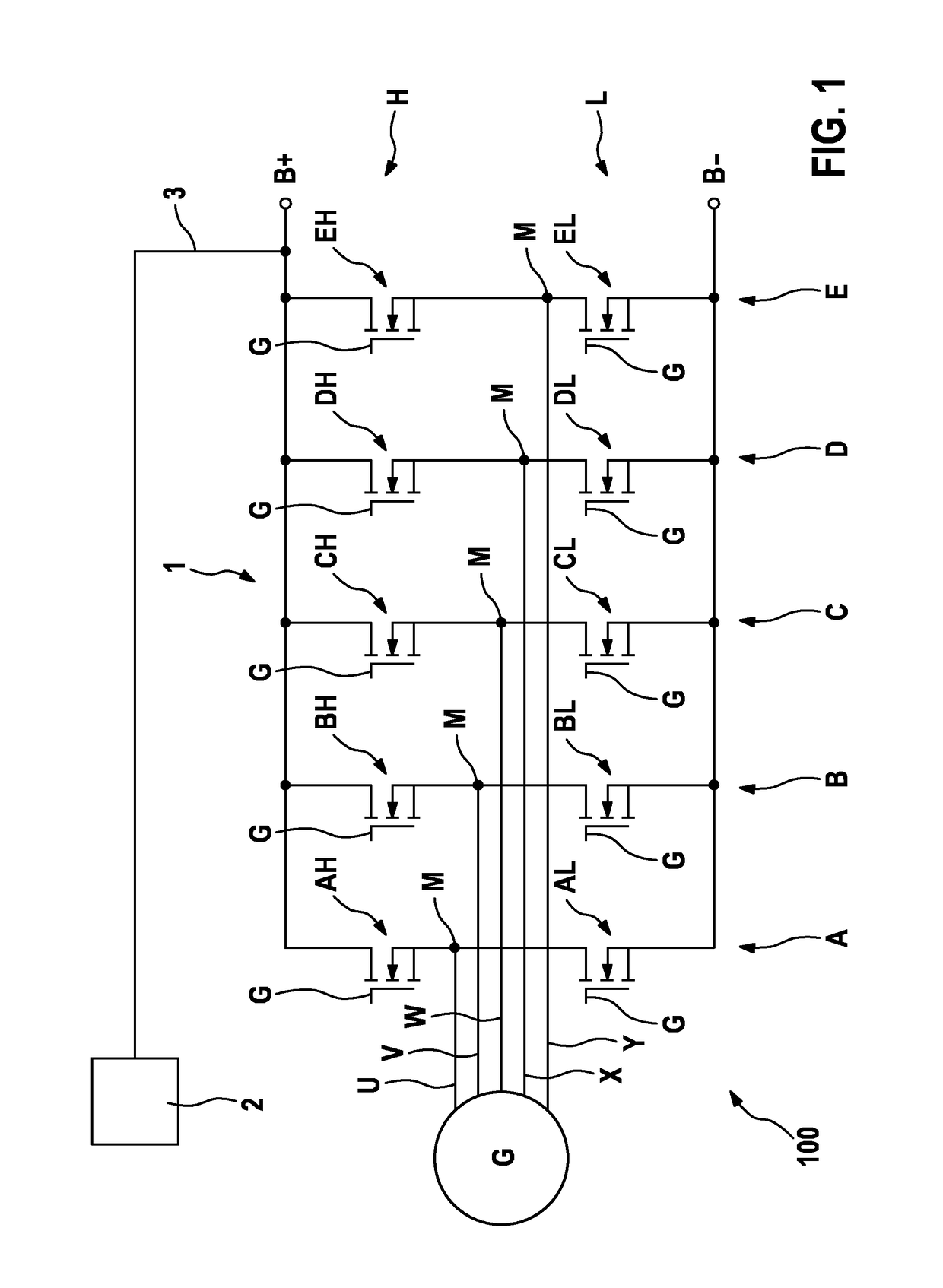
[0033]FIG. 1 schematically illustrates a conventional system which includes a bridge rectifier 1 and a generator G, using the example of a five-phase system. Bridge rectifier 1 is illustrated in FIG. 1 as a ten-pulse bridge rectifier which is configured for rectifying a three-phase current of a five-phase generator G. However, a three-, four-, six-, or seven-phase generator G and a correspondingly adapted six-, eight-, twelve-, or fourteen-pulse bridge rectifier 1, for example, may similarly also be used. Bridge rectifier 1 is part of a vehicle electrical system 100, which is only partially illustrated here.

[0034]Bridge rectifier 1 has five half bridges A through E, which are respectively connected via their center tap M to the five generator phases or corresponding phase connections U through Y.

[0035]Half bridges A through E are each connected at their ends to direct voltage terminals B+ and B−, for example battery terminals and / or corresponding supply lines of a vehicle electrical...


PUM


Abstract

A motor vehicle electrical system which includes an electric machine, an active bridge rectifier, and at least one control device, the at least one control device being configured for converting an alternating voltage which is output by the electric machine at a number of phase connections into a direct voltage by controlling active switching elements of the bridge rectifier. An arrangement is provided configured for initiating a short circuit of at least two of the phase connections as soon as a signal characterizing the direct voltage exceeds an upper threshold value, and for deactivating the short circuit as soon as the signal characterizing the direct voltage subsequently falls below a lower threshold value. An evaluation device is provided configured for detecting a value of the direct voltage, for filtering the detected value, and for providing the filtered value as the signal characterizing the direct voltage.

Description

FIELD[0001]The present invention relates to a motor vehicle electrical system, a method, and an arrangement for implementing the method.BACKGROUND INFORMATION[0002]Rectifiers of various designs may be used for feeding direct current systems out of three-phase current systems, of motor vehicle electrical systems, for example, using three-phase current generators. Bridge rectifiers having a six-, eight-, or ten-pulse design are used in motor vehicle electrical systems, corresponding to the three-, four-, or five-phase current generators which are usually installed. However, the present invention is also suitable for bridge rectifiers having other numbers of phases.[0003]When reference is made below to a generator for the purpose of simplicity, this may also be an electric machine which is operable in a generator mode and a motor mode, for example a starter generator.[0004]A so-called load dump is a critical operating condition in bridge rectifiers. A load dump occurs when, for a highl...

Claims


Application Information

Patent Timeline
Patent Type & Authority Patents(United States)
IPC IPC(8): B60L11/02H02H7/06H02H7/125H02M7/219B60L11/18H02M1/32B60L50/10
CPCB60L11/02B60L11/18H02H7/067H02M1/32H02M7/219H02H7/1252H02M2001/325B60L50/60B60L50/10H02M1/325Y02T10/70
Inventor OTTE, CHRISTOPHERMEHRINGER, PAULFEILER, WOLFGANG
Owner SEG AUTOMOTIVE GERMANY GMBH
Learn More