
Device for detecting an electromagnetic radiation

a technology for electromagnetic radiation and detection devices, applied in radiation pyrometry, instruments, electrical equipment, etc., can solve the problems of affecting the actual detection device cost, the cost of the optical system, and the sealing operation is particularly delicate and expensive, so as to improve the resolution of the signal transmitted, improve the sensitivity, and reliably and accurately measure the electromagnetic radiation

Inactive Publication Date: 2014-08-26
COMMISSARIAT A LENERGIE ATOMIQUE ET AUX ENERGIES ALTERNATIVES
View PDF11 Cites 6 Cited by
  • Summary
  • Abstract
  • Description
  • Claims
  • Application Information

AI Technical Summary

Benefits of technology

[0022]The present invention aims at a detection device enabling to reliably and accurately measure an electromagnetic radiation and, especially providing a better resolution of the signal transmitted by the detection device and an improved sensitivity.
[0023]The present invention also aims at a low-bulk and low-cost detection device.
[0024]In particular, the present invention aims at an optimized detection device comprising a large number of pixels and enabling to amplify at best a signal of IR imaging scenes, with high gains and an improved thresholding of the offset current.

Problems solved by technology

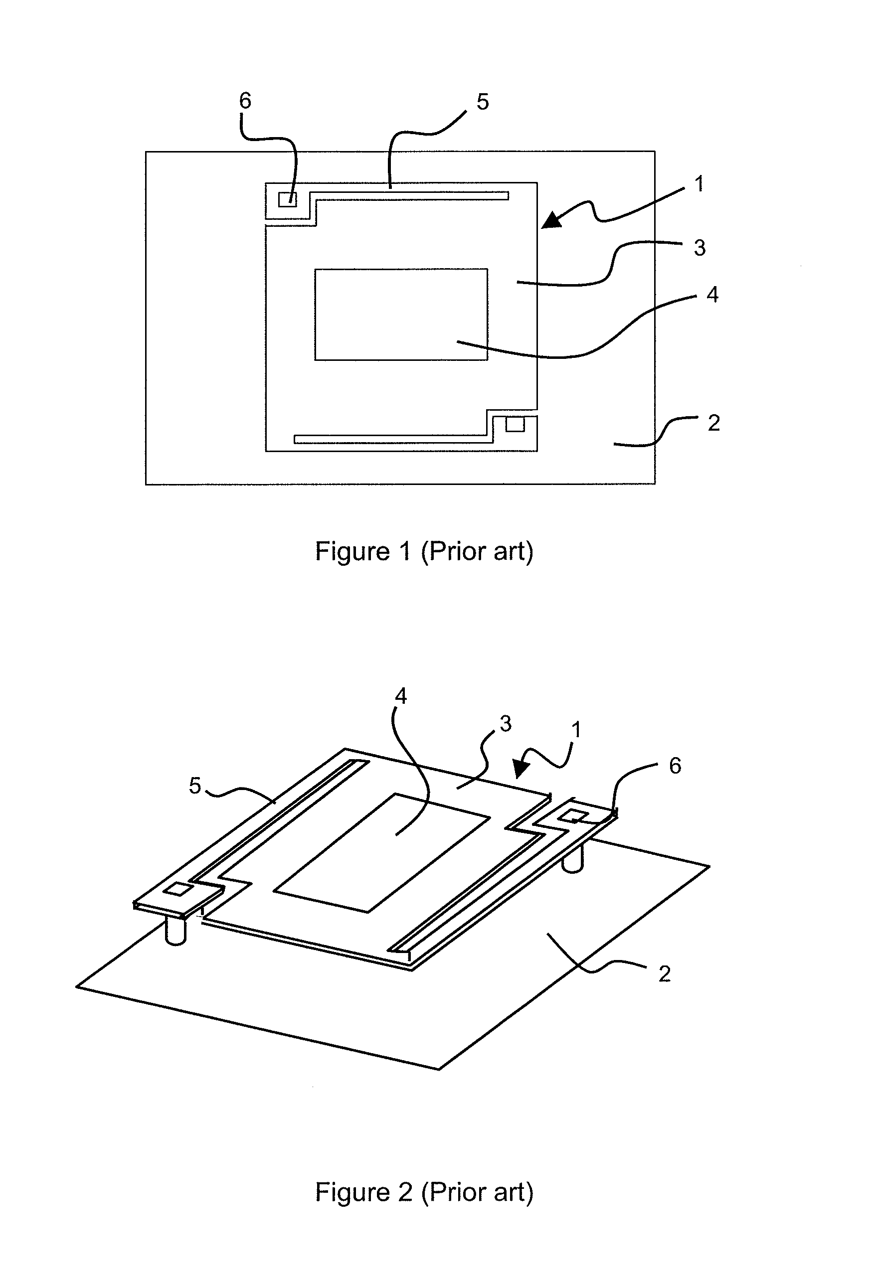
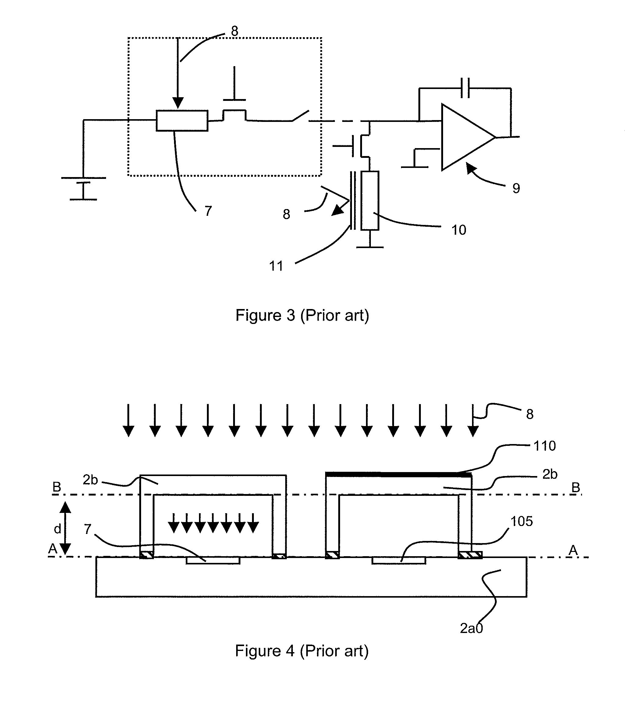
The described detection device has the disadvantage of being bulky.
Such dimensional constraints have an impact not only on the cost of the actual detection device, but also on the cost of the optical system, which has a volume depending on the size of the detection device.
Further, the sealing operation is particularly delicate and expensive since it implies manipulating a set of fragile bolometers and generally occurs in a clean room with constraining and expensive cleanness specifications.
Finally, the use of an opaque layer 11 above the reference bolometer is not sufficient to optimally suppress the offset current and accordingly does not enable to detect very low signals.
This disadvantage is particularly detrimental for IR imaging devices which require the use of high gains of detection of the IR imaging scene signal, obtained by pulsed biasing of the bolometric resistor.

Method used


Image

  • Device for detecting an electromagnetic radiation
  • Device for detecting an electromagnetic radiation
  • Device for detecting an electromagnetic radiation

Examples


Embodiment Construction

[0040]The device for detecting an electromagnetic radiation 8 preferably is a device for detecting IRs and Terahertzes (THz).

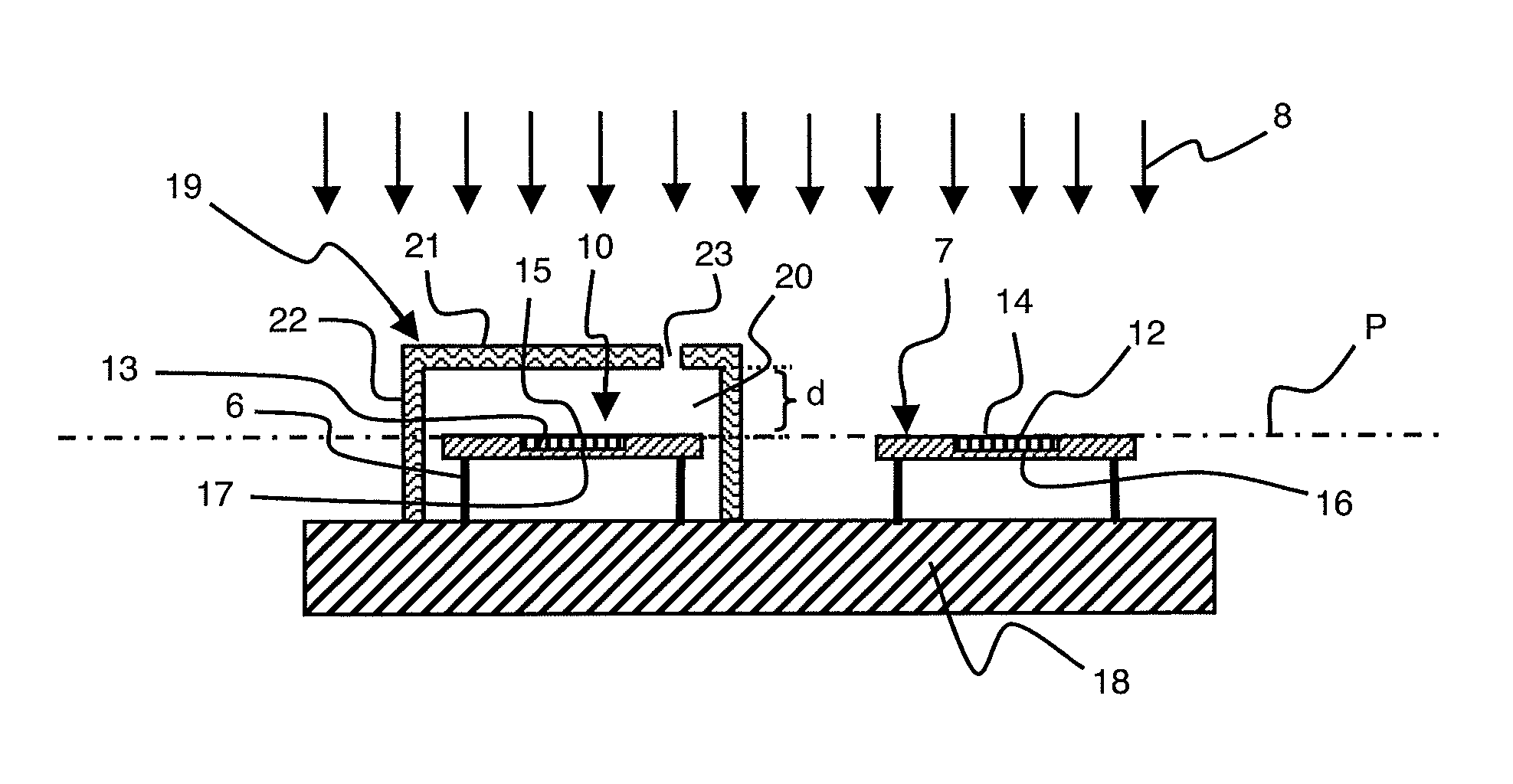
[0041]According to a first specific embodiment shown in FIG. 5, a device for detecting an electromagnetic radiation 8 comprises an active detector 7 of electromagnetic radiation 8 provided with a first element 12 sensitive to said electromagnetic radiation 8 and a reference detector 10 comprising a element 13 sensitive to said electromagnetic radiation 8.

[0042]Reference detector 10 is preferably identical to active detector 7 of electromagnetic radiation 8. The dimensional characteristics and / or the materials forming reference detector 10 are selected to obtain, for a given electromagnetic radiation, a temperature response identical to that of active detector 7.

[0043]Advantageously, active detector 7 of electromagnetic radiation 8 and reference detector 10 respectively are an active bolometer 7 of electromagnetic radiation 8 and a reference bolometer 10.

[0044]...


PUM


Abstract

The electromagnetic radiation detection device includes, on a same substrate:at least one active detector of the electromagnetic radiation provided with a first element sensitive to said radiation,at least one reference detector including a second element sensitive to said electromagnetic radiation, anda lid provided with first reflective means reflecting the incident electromagnetic radiation, said lid covering without contact the second sensitive element and defining with the substrate a cavity having the reference detector housed therein. The lid is designed to improve the sensitivity of the detection device.

Description

TECHNICAL FIELD[0001]The present disclosure relates to a device for detecting an electromagnetic radiation comprising, on a same substrate:[0002]at least one active electromagnetic radiation detector provided with a first element sensitive to said radiation,[0003]at least one reference detector comprising a second element sensitive to said electromagnetic radiation, said second sensitive element having a first main surface facing the incident electromagnetic radiation and a second main surface facing the substrate, and[0004]a lid provided with first reflective means reflecting the incident electromagnetic radiation, parallel to the first main surface of the second sensitive element, said lid covering without contact the second sensitive element and defining with the substrate a cavity having the reference detector housed therein, said active detector being outside of the cavity.STATE OF THE ART[0005]Devices for detecting an electromagnetic radiation integrate one or several electrom...

Claims


Application Information

Patent Timeline
Patent Type & Authority Patents(United States)
IPC IPC(8): G01J5/04G01J5/02G01J5/06G01J5/08G01J5/10G01J5/20
CPCG01J5/10G01J5/06G01J5/20G01J5/045G01J5/0285G01J5/02G01J5/04G01J5/046G01J2005/068G01J5/0853G01J5/068G01J5/064
Inventor YON, JEAN-JACQUESIMPERINETTI, PIERREMARY, ALEXANDRERABAUD, WILFRIED
Owner COMMISSARIAT A LENERGIE ATOMIQUE ET AUX ENERGIES ALTERNATIVES
Learn More