Image processing apparatus, image processing method, and computer program
a technology of image processing and image processing method, applied in the direction of color signal processing circuit, television system, instruments, etc., can solve the problem of inability to apply the temporal visual characteristic to each object of interes
- Summary
- Abstract
- Description
- Claims
- Application Information
AI Technical Summary
Benefits of technology
Problems solved by technology
Method used
Image
Examples
first embodiment
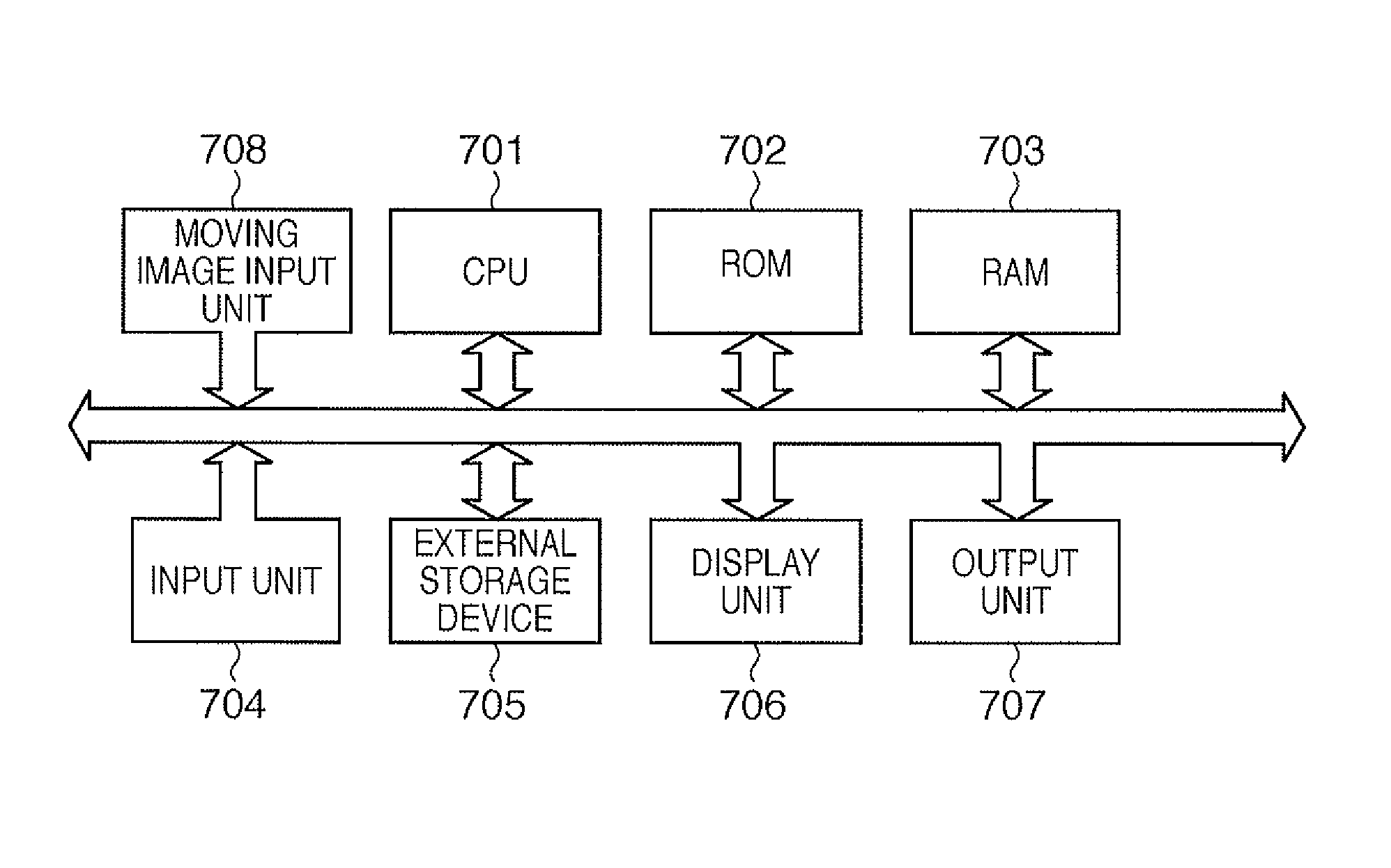
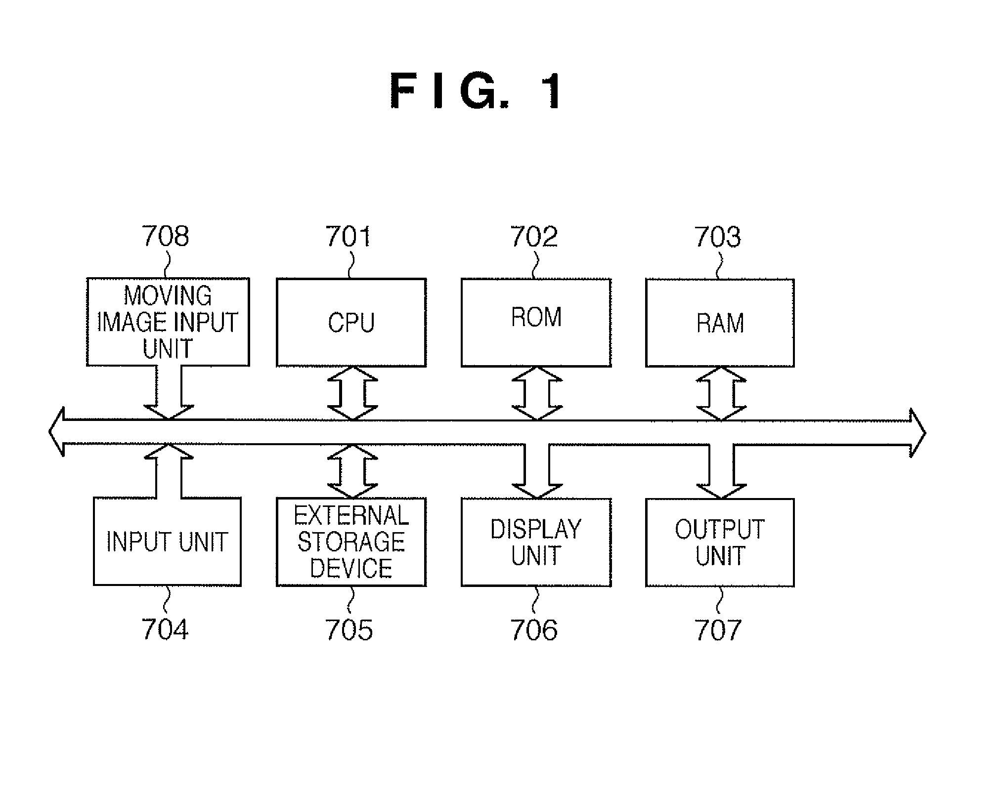
[0039]FIG. 1 is a block diagram showing an example of the block arrangement of an image processing apparatus according to this embodiment. Referring to FIG. 1, a CPU 701 controls the operation of the overall apparatus in accordance with programs stored in a ROM 702 or an external storage device 705 such as a hard disk using a RAM 703 as a work memory. The CPU 701 also executes various kinds of image processing including processing associated with color matching of this embodiment.
[0040]An input unit 704 indicates input devices such as a keyboard and a mouse and their input interfaces and receives an input instruction from the operator. A display unit 706 represents a display device such as a monitor and a video interface and displays a moving image or a user interface window associated with the embodiment. An output unit 707 represents an output device such as a printer and an output device interface.
[0041]A moving image input unit 708 is a processing unit which receives moving imag...
second embodiment
[0103]The second embodiment of the present invention will be described below. In the above-described first embodiment, a frame image itself is held in the storage unit, and the object image position information 503 shown in FIG. 4 is used to acquire an object image in the frame image. As a characteristic feature of the second embodiment, an object image is held independently of a frame image.
[0104]FIG. 10 shows an example of a frame image information table according to the second embodiment. It is different from the frame image information table shown in FIG. 3 of the above-described first embodiment in that no frame low-pass image (frame low-pass image address information 405 in FIG. 3) is held.
[0105]FIG. 11 shows an example of an object information table according to the second embodiment. As a characteristic feature of the second embodiment, the object information table shown in FIG. 11 holds the information of object images and object low-pass images for all objects including a ...
third embodiment
[0110]The third embodiment of the present invention will be described below. The same arrangements as in FIGS. 1 to 3 are applied, and a description thereof will not be repeated. As a characteristic feature of the third embodiment, an object feature amount is calculated, unlike the first and second embodiments.
[0111]As shown in FIG. 13, the object information table of this embodiment stores items to be described below. The same reference numerals as in FIG. 4 denote the same parts in FIG. 13, and a description thereof will not be repeated. As a characteristic feature, the object information table includes object feature amount information 1304 representing, for example, the moving speed and size of an object, unlike FIG. 4.
[0112]204)>
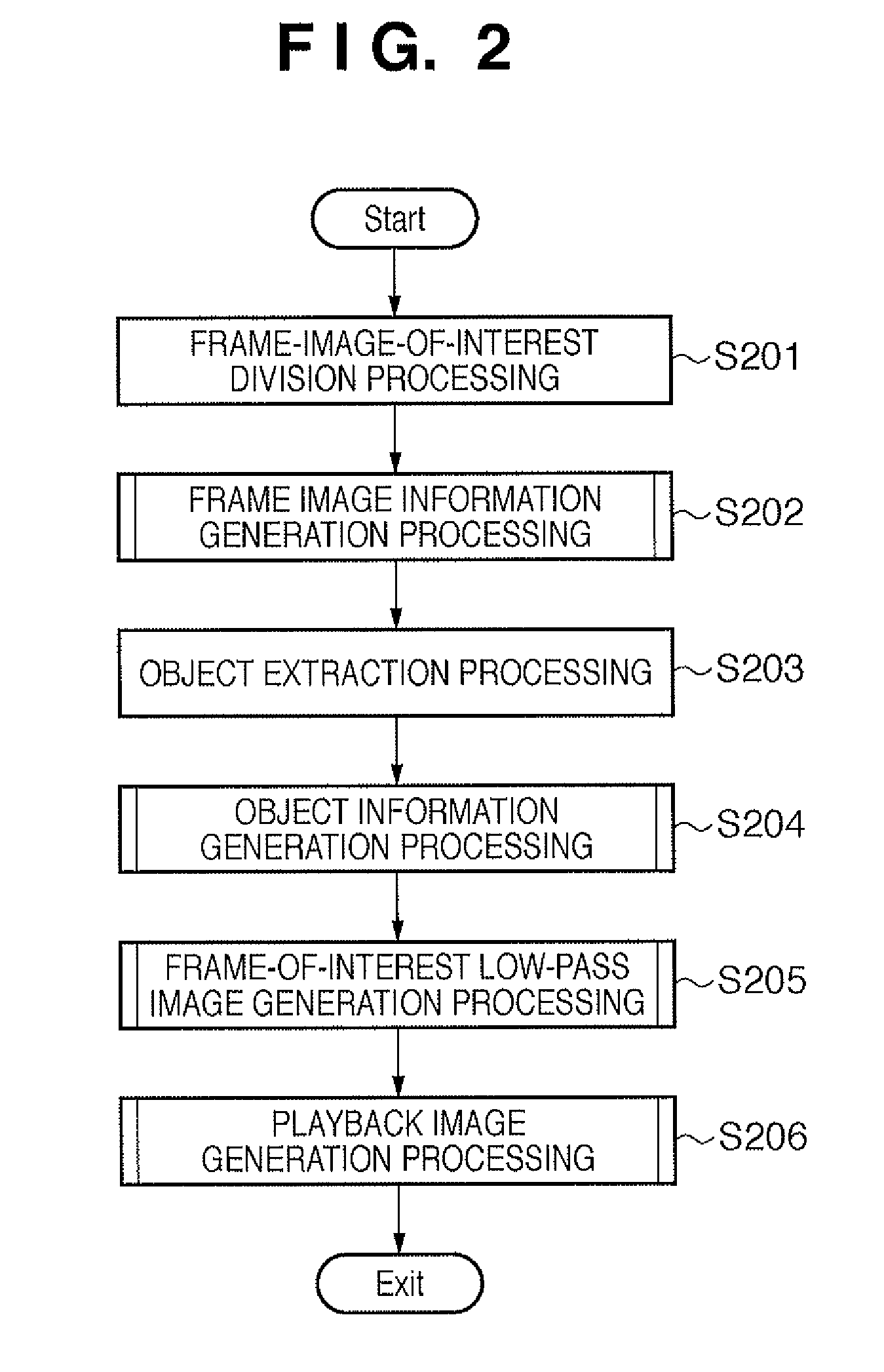
[0113]FIG. 14 is a flowchart illustrating the sequence of object information generation processing in step S204 of FIG. 2. First, it is determined whether object image data extracted by the object extraction processing in step S203 is already registered...
PUM
 Abstract
Description
Claims
Application Information
 - R&D
- Intellectual Property
- Life Sciences
- Materials
- Tech Scout
- Unparalleled Data Quality
- Higher Quality Content
- 60% Fewer Hallucinations
Browse by: Latest US Patents, China's latest patents, Technical Efficacy Thesaurus, Application Domain, Technology Topic, Popular Technical Reports.
© 2025 PatSnap. All rights reserved.Legal|Privacy policy|Modern Slavery Act Transparency Statement|Sitemap|About US| Contact US: help@patsnap.com


