Multiple-output dual-polarity DC/DC converters and voltage regulators

a dual-polarity dc/dc converter and voltage regulator technology, applied in the direction of dc-dc conversion, power conversion systems, instruments, etc., can solve the problems of low power dissipation in the switch, unfavorable unity transfer characteristics of boost converters, and unwanted strays

Inactive Publication Date: 2014-09-02
ADVANCED ANALOGIC TECHNOLOGIES INCORPORATED
View PDF5 Cites 112 Cited by
  • Summary
  • Abstract
  • Description
  • Claims
  • Application Information

AI Technical Summary

Benefits of technology

[0037]In one embodiment the power MOSFETs connecting the inductor to the positive outputs utilize either P-channel or N-channel MOSFETs with circuitry to prevent forward biasing of any diode between the MOSFETs source and drain terminals. In a preferred embodiment the MOSFET connected to the highest positive output voltage includes a source-body short and an intrinsic diode parallel to its source and drain terminals.
[0039]In one embodiment the power MOSFETs connecting the inductor to the negative outputs utilize either P-channel or N-channel MOSFETs with circuitry to prevent forward biasing of any diode between the MOSFETs source and drain terminals. In a preferred embodiment the MOSFET connected to the most negative output voltage includes a source-body short and an intrinsic diode parallel to its source and drain terminals.

Problems solved by technology

Excepting switching transients, the ID·VDS product in the power MOSFET remains small, and power dissipation in the switch remains low.
The disadvantage of transformers is they are large compared to single-winding inductors and suffer from unwanted stray inductances.
While this equation describes a wide range of conversion ratios, the boost converter cannot smoothly approach a unity transfer characteristic without requiring extremely fast devices and circuit response times. For high duty factors and conversion ratios, the inductor conducts large spikes of current and degrades efficiency.
Space limitations preclude the use of so many switching regulators each with separate inductors.
Unfortunately, multiple output non-isolated converters capable of generating both positive and negative supply voltage require multiple winding or tapped inductors.
While smaller than isolated converters and transformers, tapped inductors are also substantially larger and taller in height than single winding inductors, and suffer from increased parasitic effects and radiated noise.
As a result multiple winding inductors are typically not employed in any space sensitive or portable device such as handsets and portable consumer electronics.
While the efficiency of the low-drop-out linear regulators, or LDOs, is often worse than the switching regulators, they are much smaller and lower in cost since no coil is required.

Method used


Image

  • Multiple-output dual-polarity DC/DC converters and voltage regulators
  • Multiple-output dual-polarity DC/DC converters and voltage regulators
  • Multiple-output dual-polarity DC/DC converters and voltage regulators

Examples


Embodiment Construction

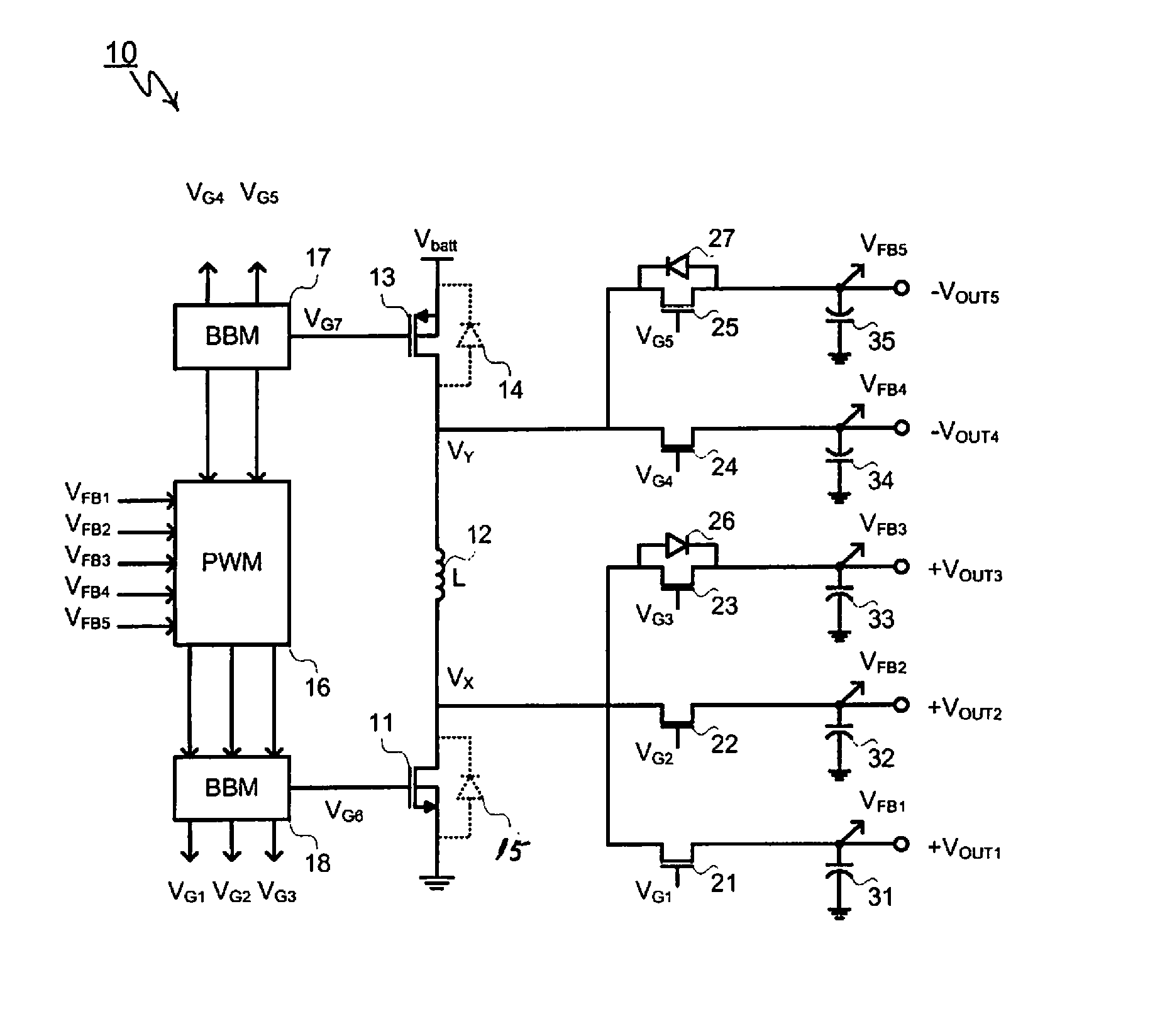
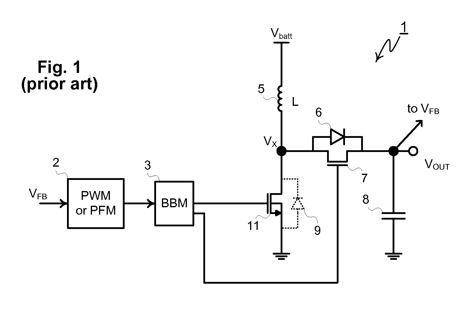
[0054]As described previously, conventional non-isolated switching regulators require one single-winding inductor and corresponding dedicated PWM controller for each regulated output voltage and polarity. In contrast, this disclosure describes an inventive boost converter able to produce multiple independently-regulated outputs of opposite polarity, i.e. one or more positive above-ground outputs and one or more negative below-ground output from one single-winding inductor.

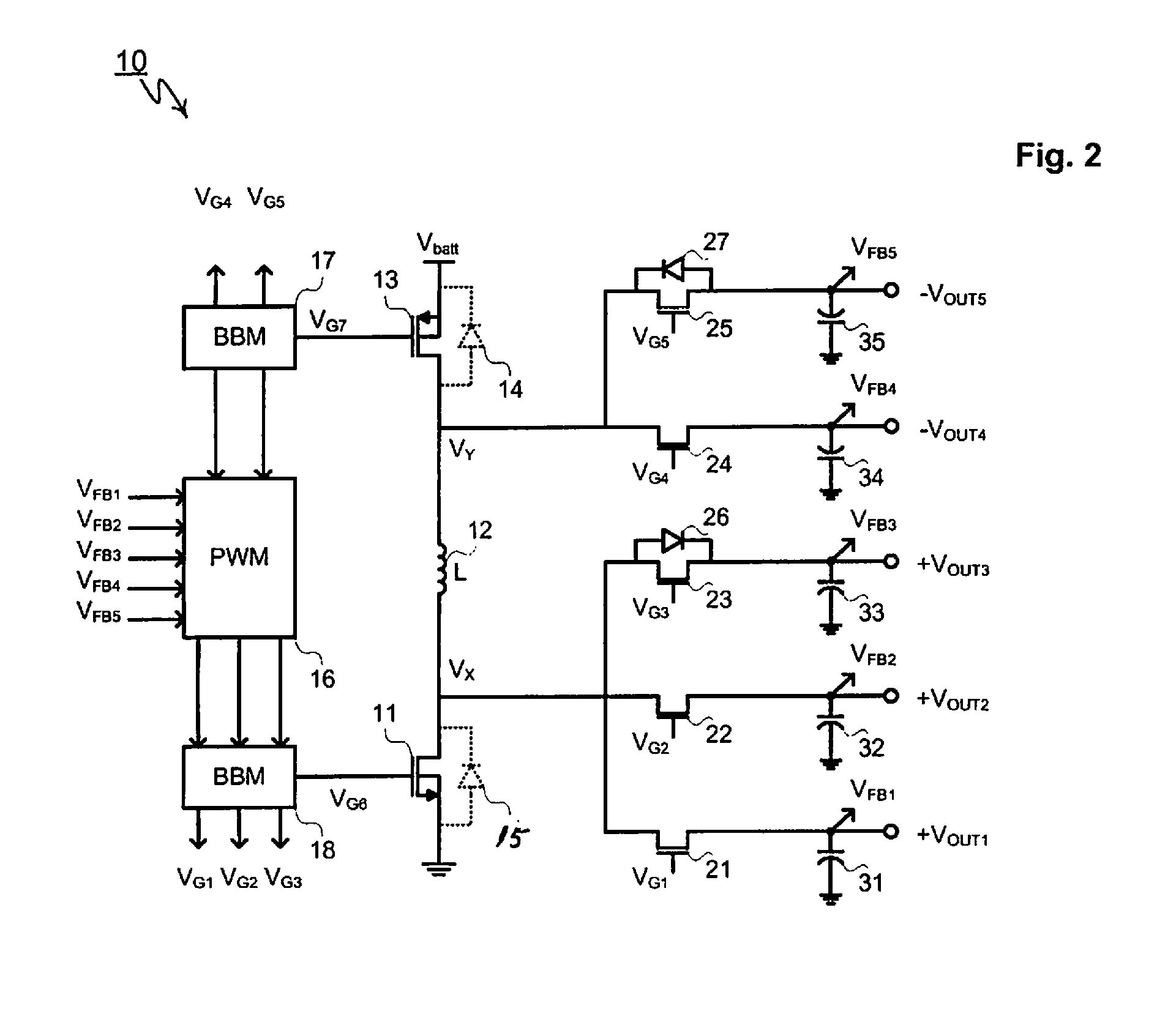
[0055]Shown in FIG. 2, a five-output dual polarity inductive boost converter 10 comprises low-side N-channel MOSFET 11, inductor 12, high-side P-channel MOSFET 13, floating positive-output synchronous rectifier 23 with intrinsic source-to-drain diode 26, floating positive-output synchronous rectifiers 22 and 21 with no parallel source-drain diodes, floating negative-output synchronous rectifier 25 with intrinsic source-to-drain diode 27, floating negative-output synchronous rectifier 24 with no parallel source-drai...


PUM


Abstract

A multi-output dual polarity inductive boost converter includes an inductor, a first output node, a second output node, and a switching network, the switching network configured to provide the following modes of circuit operation: a first mode where the positive electrode of the inductor is connected to an input voltage and the negative electrode of the inductor is connected to ground; 2) a second mode the negative electrode of the inductor is connected to ground and the positive electrode of the inductor is connected in sequence to one or more of the fourth and fifth output nodes; and 3) a third mode where the positive electrode of the inductor is connected to the input voltage and the negative electrode of the inductor is connected in sequence to one or more of the first, second and third output nodes.

Description

BACKGROUND OF THE INVENTION[0001]Voltage regulation is commonly required to prevent variation in the supply voltage powering various microelectronic components such as digital ICs, semiconductor memory, display modules, hard disk drives, RF circuitry, microprocessors, digital signal processors and analog ICs, especially in battery powered application likes cell phones, notebook computers and consumer products.[0002]Since the battery or DC input voltage of a product often must be stepped-up to a higher DC voltage, or stepped-down to a lower DC voltage, such regulators are referred to as DC-to-DC converters. Step-down converters are used whenever a battery's voltage is greater than the desired load voltage. Step-down converters may comprise inductive switching regulators, capacitive charge pumps, and linear regulators. Conversely, step-up converters, commonly referred to boost converters, are needed whenever a battery's voltage is lower than the voltage needed to power its load. Step-...

Claims


Application Information

Patent Timeline
Patent Type & Authority Patents(United States)
IPC IPC(8): G05F1/00H02M1/00
CPCH02M3/33561H02M3/158H02M2001/009H02M1/009H02M3/1584
Inventor WILLIAMS, RICHARD
Owner ADVANCED ANALOGIC TECHNOLOGIES INCORPORATED
Why Eureka
Try Eureka